 | –≠–ª–µ–∫—Ç—Ä–æ–Ω–Ω—ã–π –∫–æ–º–ø–æ–Ω–µ–Ω—Ç: CS5820 | –°–∫–∞—á–∞—Ç—å:  PDF PDF  ZIP ZIP |

21:3 LVDS Transmitter
CS5820
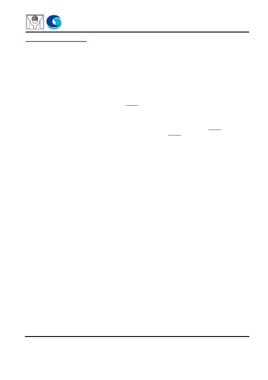
BLOCK DIAGRAM
GENERAL DESCRIPTION
Myson-Century Technology
FEATURES
USA:
4020 Moorpark Avenue Suite
San Jose, CA, 95117
Tel: 408-243-8388 Fax: 408-243-3188
Sales@myson.com.tw
www.myson.com.tw
Rev.1.6 October 2001
page 1 of 12
Myson-Century Technology, Inc.
Taiwan:
No. 2, Industry East Rd. III,
Science-Based Industrial Park, Hsin-Chu, Taiwan
Tel: 886-3-5784866 Fax: 886-3-5784349
CS5820 receives three sets of 7-bit data in CMOS
logic level and convert them into three low-voltage
differential signaling (LVDS) serial channels. The 7-
bit input data is referenced to the CKIN signal. The
RF pin selects either rising or falling edge trigger of
CKIN. Parallel to serial conversion is performed by a
7X internal generated clock reference using on-chip
PLL using CKIN. A copy of CKIN but phase-locked to
the output serial streams, CLKOUT, is also
converted to the fourth LVDS channel. CS5820
offers a reliable communication media using LVDS
signaling and provides low EMI dealing with wide,
high-speed TTL interfaces.
This is especially attractive for interfaces between
GUI controller and display systems such as LCD
panels for SVGA/XGA/SXGA applications.
∑ Three 7-bit serial and one clock LVDS channels.
∑ Compatible with ANSI TIA/EIA-644 LVDS stan-
dard.
∑ Wide CKIN ranges from 31MHz to 68MHz.
∑ Fully integrated on-chip PLL that provides 7X
CKIN serial shift clock.
∑ Pin selectable for rising or falling edge trigger.
∑ Support power-down mode.
∑ 5V/3.3V tolerant data input.
∑ Single 3.3V supply operation.
∑ CMOS low power consumption.
∑ Functional compatible with DS90C363 and
SN75LVDS84.
∑ Available in 48-pin TSSOP package.
PARALLEL-IN SERIAL-OUT
D0-D6
7-Bit SHIFT REGISTER
SHIFT/LOAD_N
CLK
DIN
PARALLEL-IN SERIAL-OUT
7-Bit SHIFT REGISTER
SHIFT/LOAD_N
DIN
PARALLEL-IN SERIAL-OUT
7-Bit SHIFT REGISTER
SHIFT/LOAD_N
DIN
CLK
CLK
PHASE LOCK LOOP
R/F
CLK
7xCLK
SHIFT/LOAD_N
CONTROL LOGIC
D7-D13
D14-D20
RF
CKIN
SHTDN
EN
Y0P
Y0N
EN
Y1P
Y1N
EN
Y2P
Y2N
EN
CKOP
CKON
CS5820

CS5820
Myson-Century Technology
page 2 of 12
PIN CONNECTION DIAGRAM
Figure-1 48-pin TSSOP
1
2
3
4
5
6
7
8
9
10
11
12
13
14
15
16
17
18
19
20
21
22
23
24
D4
VDD
D5
D6
VSS
D7
D8
VDD
D9
D10
VSS
D11
D12
RF
D13
D14
VSS
D15
D16
D17
VDD
D18
D19
VSS
CS5820
48
47
46
45
44
43
42
41
40
39
38
37
36
35
34
33
32
31
30
29
28
27
26
25
D3
D2
VSS
D1
D0
NC
LVDS_VSS
Y0N
Y0P
Y1N
Y1P
LVDS_VDD
LVDS_VSS
Y2N
Y2P
CKON
CKOP
LVDS_VSS
PLL_VSS
PLL-VDD
PLL_VSS
SHTDN
CKIN
D20

CS5820
Myson-Century Technology
page 3 of 12
PIN DESCRIPTION
Name
I/O
Description
D[0-6]
I
Parallel data input for Y0 LVDS channel. D[0] is LSB and D[6] is MSB. MSB is shifted out
first.
D[7-13]
I
Parallel data input for Y1 LVDS channel. D[7] is LSB and D[13] is MSB.
D[14-20]
I
Parallel data input for Y2 LVDS channel. D[14] is LSB and D[20] is MSB.
CKIN
I
Parallel input clock.This clock signal is used for parallel data reference. It is also used by
the on-chip PLL to generate the 7X shift clock for parallel to serial conversion.
RF
I
Rise/fall select. This pin selects the polarity of the CKIN edge for data input. RF = 1
selects CKIN rise edge, and RF = 0 selects CKIN fall edge.
SHTDN
I
Shutdown control (low active). When SHTDN is low, the internal PLL is put into inhibit
mode and all LVDS output channels are shut off. This also resets all internal registers.
For normal operation, SHTDN should be set to high.
Y0P,
Y0N
O
Y0 LVDS channel output. These are differential LVDS outputs for Y0 channel
corresponds to D[0-6].
Y1P,
Y1N
O
Y1 LVDS channel output. These are differential LVDS outputs for Y1 channel
corresponds to D[7-13].
Y2P,
Y2N
O
Y2 LVDS channel output. These are differential LVDS outputs for Y2 channel
corresponds to D[14-21].
CKOP,
CKON
O
Clock LVDS channel output. These are differential LVDS output for the replica of CKIN
signal. CKOP and CKON are derived from the internal phase lock loop and phase
aligned with the serial data output and can be used by the LVDS receiver for reference
edge.
PLL_VDD
P
Power supply for PLL circuit.
PLL_VSS
P
Power ground for PLL circuit.
LVDS_VDD
P
Power supply for output buffer circuits.
LVDS_VSS
P
Power ground for output buffer circuits.
VDD
P
Power supply for internal circuits.
VSS
P
Power ground for internal circuits.
CS5820
Myson-Century Technology
page 4 of 12
FUNCTIONAL DESCRIPTION
Control logic
There are two modes in this circuit. One is normal mode, and another is power down mode. Two modes are
controlled by the control signal "SHTDN". If SHTDN is high, the circuit is in the normal mode, else if low, the
circuit is in the power down mode. In the power down mode, every block is off to make sure the least power
consumption.
7 x CLK PLL
7 x CLK PLL, which is a phase lock loop, generates seven times clock of CKIN. The signal "RF" indicates that the
input data (D0 ~ D20) is rising edge or falling edge trigger by CKIN. If RF=1, it is rigging edge trigger, else if
RF=0, it is falling trigger. This seven times clock of CKIN is used by the Parallel ~ LOAD 7 Bit shift Register. 7 x
CLK PLL also generate the control signal "SHIFT/LOAD". This signal is also used by the Parallel ~ LOAD 7 Bit
Shift Register to indicate when to load data or shift data.
Parallel ~ LOAD 7 Bit shift Register
This block transfers 7 bits parallel data into one bit series data out. It is controlled by SHIFT/LOAD. If this control
signal is low, the data are loaded into shift registers. Next, the SHIFT/LOAD turns high to shift data from shift
register to output buffer seven times. One load and then seven shift.
Ref:
There are two properties in this block. One is that it supports reference voltage to fine the output's common mode
voltage. Another is that it generates about (4ns ~6ns) pulse width's power on reset signal. When power on, all
block would be reset by power on reset signal to make sure that the circuit would not stuck-at some situation we
do not care.
Output buffer
There are three data output buffers and one clock output buffer. Output buffer generates differential pair output
that swing is under 500 ~ 900mV, and common-mode voltage is under 1.125V ~ 1.375V.
CS5820
Myson-Century Technology
page 5 of 12
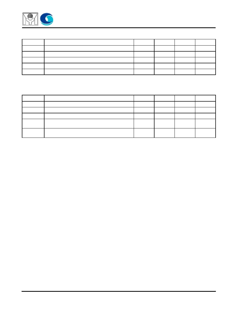
RECOMMENDED OPERATING CONDITIONS
TIMING REQUIREMENTS
Symbol
Parameter
Min
Typ
Max
Unit
V
CC
Supply voltage
3
3.3
3.6
V
V
IH
High-level input voltage
2
-
-
V
V
IL
Low-level input voltage
-
-
0.8
V
Z
L
Differential load impedance
90
-
132
T
A
Operating free-air temperature
0
-
70
∞
C
Symbol
Parameter
Min
Typ
Max
Unit
t
C
Input clock period
14.7
32.4
ns
t
W
Pulse duration, high-level input clock
0.4t
C
0.6t
C
ns
t
t
Transition time, Input signal
5
ns
t
su
Setup time, data, D0~D20 valid before CKIN
(RF = 0)
or CKIN
(RF = 1)
3
ns
t
h
Hold time, data, D0~D20 valid after CKIN
(RF = 0) or
CKIN
(RF = 1)
1.5
ns