 | –≠–ª–µ–∫—Ç—Ä–æ–Ω–Ω—ã–π –∫–æ–º–ø–æ–Ω–µ–Ω—Ç: CS8552V | –°–∫–∞—á–∞—Ç—å:  PDF PDF  ZIP ZIP |

BLOCK DIAGRAM
GENERAL DESCRIPTION
FEATURES
CS8552
TV Encoder
USA:
4020 Moorpark Avenue Suite 115
San Jose, CA, 95117
Tel: 408-243-8388 Fax: 408-243-3188
Sales@myson.com.tw
www.myson.com.tw
Rev. 1.3 January 2003
page 1 of 25
Myson Century, Inc.
Taiwan:
No. 2, Industry East Rd. III,
Science-Based Industrial Park, Hsin-Chu, Taiwan
Tel: 886-3-5784866 Fax: 886-3-5784349
The CS8552 provides full conversion from digital
video format YCbCr into NTSC/PAL composite and
S-video. It can be used in VCD, DVD, and digital
VCR applications.
Two times oversampling reduces the output filter
requirements and guarantees no alias interference
by internal UV filters and Y filter.
Two 9-bit DACs provide two channels for a S-
video output port or two composite video outputs with
high quality image.
32-pin package and pin assignment make the
CS8552 compatible with major vendors.
∑ Especially designed for VCD, Karaoke, digital
VCR, DVD, DIGITAL set-top box.
∑ Supports the following 4 modes:
NTSC, PAL-M, PAL-BDGHI, PAL-Nc.
∑ 8-bit 4:2:2 YCbCr inputs for glueless interface to
MPEG decoders.
∑ CVBS (composite YC) or S-video (Y and C)
outputs.
∑ Supports CCIR-601 format, non-square pixel
∑ 2x oversampling simplifying external filtering.
∑ 6MHz and 1.3MHz anti-alias filters for Y and U/V
channels each.
∑ 2 channels of 9-bit DAC.
∑ Supports master and slave modes.
∑ Supports interlace operation only.
∑ Automatic mode detection/switching in slave
mode.
∑ 3.3V supply voltage; 5V tolerant for all digital I/O
pins.
VIDEO-TIMING
CONTROLLER
SUB-CARRIER
GENERATION
SINE-TABLE
SERIAL
TO
PARALLEL
4:2:2 to
4:4:4
INTER-
u-FILTER
v-FILTER
y-FILTER
POLATION
H, V-SYNC
CLK_27
SLEEP
P[7:0]
MODE[3:0]
SVIDEO
MASTER
CBSWAP
COLOR-BURST
&
MODULATION
&
MIXER
CVBS/Y
CVBS/C
DAC-
MAPPING
VREF_O
FSADJUST
COMP
DAC
DAC
page 2 of 25
CS8552
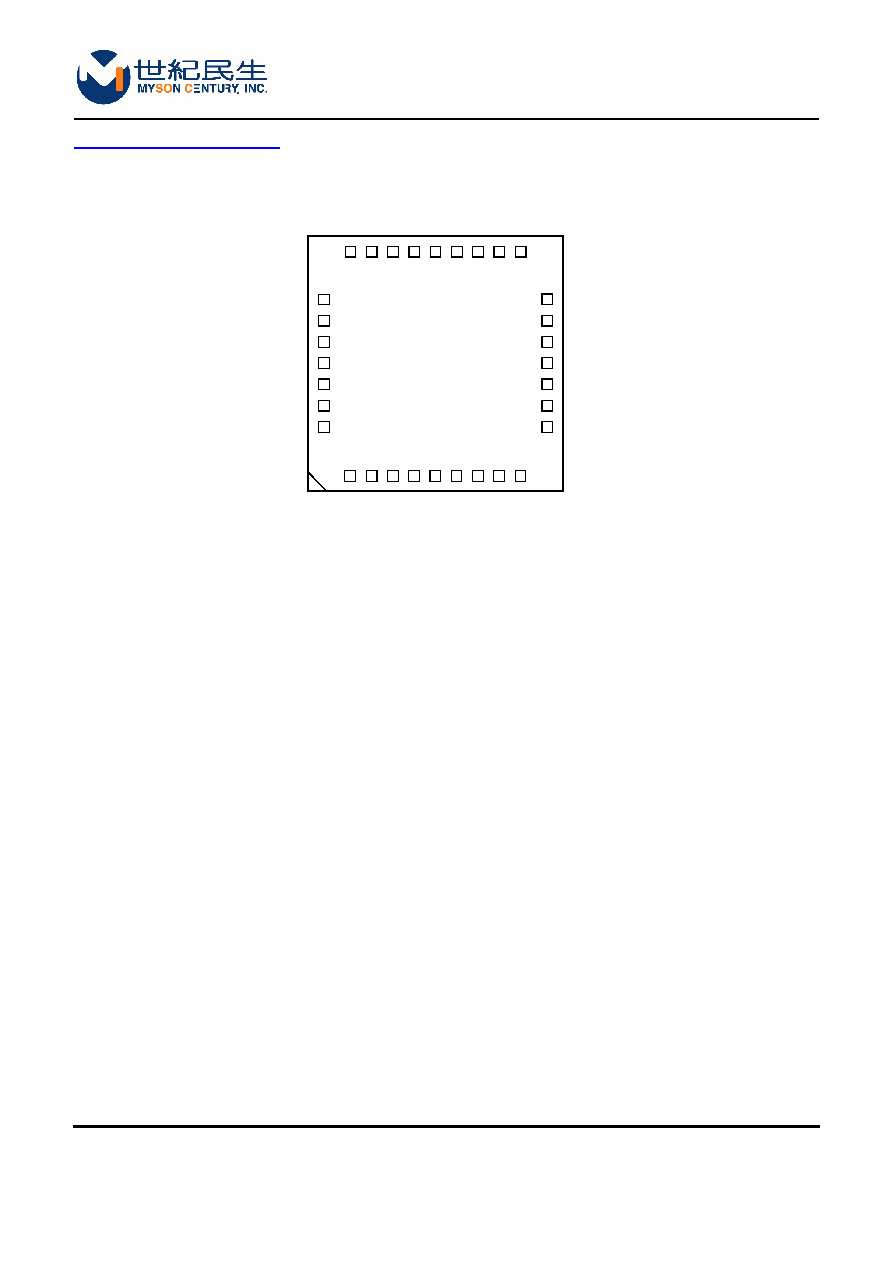
PIN CONNECTION DIAGRAM
Figure-1 32-pin PLCC
CS8552V
30
31
32
1
2
3
4
20
19
18
17
16
15
14
5
6
7
8
9
10
11
12
13
29
28
27
26
25
24
23
22
21
CL
K_
2
7
P7
P6
P5
P4
P3
P2
P1
P0
FA
D
J
I
COMPI
VA
A
VREFO
VREF
I
NC
CVBSC
VSS
SL
EEP
MD0
MD1
MD2
MD3
MASTERI
CBSWAPI
SVIDEOI
VSS
VDD
VSYNC
HSYNC
NC
VSS
CVBSY
page 3 of 25
CS8552
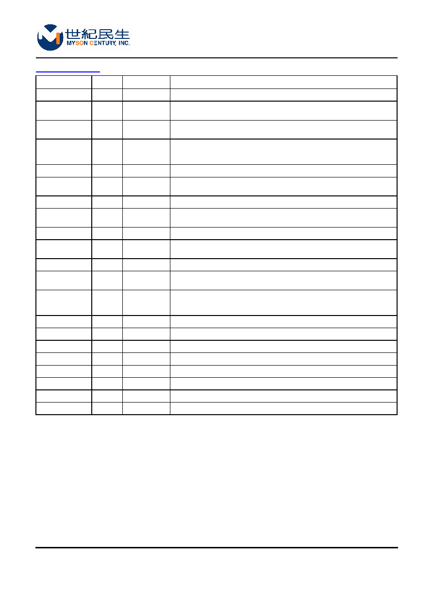
PIN DESCRIPTION
Name
I/O
PLCC Pin No.
Description
CLK_27
I
29
Pixel clock, 27MHz, twice the Y sample rate
VSYNC
I/O
32
Vertical sync, output in master mode or input in slave mode, is synchronized
by CLK.
HSYNC
I/O
1
Horizontal sync, output in master mode or input in slave mode, is
synchronized by CLK too.
P[7:0]
I
28-21
YCbCr pixel inputs (TTL compatible). Also, synchronized by CLK with
respect to the incoming HSYNC timing, the higher index corresponds to a
greater significance.
MD[3:0]
I
17-20
Configuration inputs
MASTER
I
16
in 0: slave mode, h and v sync are inputs. 1: master mode, h and v sync are
outputs.
CBSWAP
I
15
0: normal Cr, Cb sequence. 1: swaps Cr, Cb sequence
SVIDEO
I
14
0: composite output same signal on both Y, C channels, 1: s-video output, Y,
C channels.
SLEEP
I
13
1: power down, reset 0: normal operation
FSADJUST
I
5
Full scale adjust control pin. A resistor RSET is connected to GND. Used to
control the full-scale output current on analog outputs.
COMP
I
6
Compensation pin. A 0.1
µ
µ
µ
µ
F capacitor is used to bypass this pin to VCC.
VREFO
I
8
Voltage reference output, typically 1.2V, may be used to connect to VREFI
input.
VREFI/VRDAC
I
9
Voltage reference input, typically 1.235V. A 0.11
µ
µ
µ
µ
F capacitor must be used
to decouple this input to GND. DAC current switch reference input, connect
to VREFO output.
NC
O
10
No connection
CVBS/C
O
11
Composite output or chrominance
CVBS/Y
O
4
Composite output or luminance (with blanking and sync)
VAA
7
Analog power
VDD
31
Digital power
GND
30
Digital ground
AGND
3, 12
Analog ground
NC
2
No connection

page 4 of 25
CS8552
FUNCTIONAL DESCRIPTION
MODE configuration
SeeTable 1 to Table 3 for details.
master = 1: master mode
Horizontal sync and vertical sync are generated from internal timing and are output at the rising edge of
clk_27.
md[3]: Defines EFIELD function
0: vsync is output pin
1: vsync is even/odd field indicator, vsync=0 even, vsync=1 odd.
md[2]: Defines PAL625 function
0: 525-line operation is set.
1: 626-line operation is set.
master = 0: slave mode
Horizontal sync and vertical sync are inputs that are synchronized by clk_27.
A falling edge of VSYNC* occurring within ±1/4 of a scan line from the falling edge of HSYNC* cycle time
indicates the beginning of Field-1. A falling edge of VSYNC* occurring within ±1/4 of a scan line from the
middle point of the line indicates the beginning of Field-2. See Figure 2.
Figure-2
md[3]: Defines YCSWAP
0: normal operation.
1: Swap the luma and chroma samples.
md[2]: Defines SETUP function
0: 7.5 IRE setup is enabled for NTSC and PAL-M, with scaling for 92.5% black-to-white range,
other PALs with normal 100% black-to-white range.
1: 7.5 IRE setup is disabled for NTSC and PAL-M, with scaling for 100% black-to-white range.
md[1]: Defines PALSA function, South America.
0: Normal operation.
1: PAL-M used for Brazil 525 lines operation. PAL-Nc used for Argentina 625 lines
operation.
Field-1
Field-2

page 5 of 25
CS8552
Table-1
EFIELD
EFIELD is used when configured as a master. When EFIELD is set low, the Normal vsync* signal is
output on the VSYNC* pin. When EFIELD is set high, field ID information is output on the VSYNC*
pin (VSYNC* low for Field-1 and high for Field-2)
PAL625
PAL625 is used when configured as a master. When PAL625 is set low, 525-line operation is
selected. When PAL625 is set high, 625-line operation is selected. This mode is set by automatic
detection when configured as a slave.
YCSWAP
YCSWAP should normally be set to zero. When configured as a slave, this bit can be set high to
swap the luma and chroma samples, thus altering the pixel sequence with respect to the incoming
HSYNC* timing reference.
SETUP
SETUP is normally low for the common video modes. The setup and scaling function is toggled
when this bit is high. When SETUP is low, the 7.5IRE setup is enabled for NTSC and PAL-M with
scaling amplified for a 92.5% black-to-white range. When SETUP is high, the 7.5 IRE setup is
disabled for NTSC and PAL-M with 100% black-to-white range scaling. Other PAL formats have
setup disabled with normal 100% scaling.
PALSA
PALSA is normally low for the common video modes. South American video Standards can be
enabled by setting this bit high. For 525-line operation, the PALSA enables PAL-M for Brazil; in 625-
line operation, the PALSA enables PAL-Nc for Argentina.
Table-2
Master mode:
Table-3
Slave mode:
Mode
Mode[3]
Mode[2]
Mode[1]
Mode[0]
Slave
YCSWAP
SETUP
PALSA
RESERVED
Master
EFIELD
PAL625
RESERVED
RESERVED
master
Mode[3:0]
System
PAL-625
PALSA
Fv Hz
Fh Hz
1
X000
(Normal setup) NTSC
0
0
59.94
15734.26
0
1
X010
X010
X010
PAL-M
0
1
59.94
15734.26
1
X100
PAL-BDGHI
1
0
50.00
15625
0
1
X010
X010
X110
PAL-Nc
1
1
50.00
15625
Master
Mode[3:0]
System
PAL-625
PALSA
Fv hz
Fh Hz
0
X000
NTSC
0
0
59.94
15734.26
0
X010
PAL-M
0
1
59.94
15734.26
0
X000
PAL-BDGHI
1
0
50.00
15625
0
X010
PAL-Nc
1
1
50.00
15625