LF
40
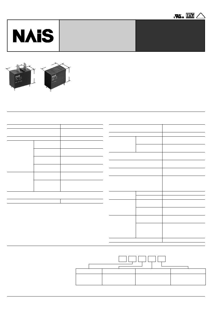
TMP type
PCB type
mm
inch
30.1
1.185
23.3
.917
15.7
.618
23.3
.917
30.1
1.185
15.7
.618
FEATURES
1. Ideal for compressor and inverter
loads
1) Compressor load: 20A 250V AC
2)
Inverter load: 20A 100V AC, 10A 200V AC
2. High insulation resistance
∑ Creepage distance and clearances
between contact and coil;
Creepage Min. 9.5mm
.374inch
/Clear-
ance Min. 8mm
.315inch
∑ Surge withstand voltage: Min. 10,000V
3. "PCB" and "TMP" types available
4. Conforms to the various safety
standards:
UL/CSA, TÐV, VDE approved
SPECIFICATIONS
Contact
Coil
Characteristics
Arrangement
1 Form A
Initial contact resistance, max.
(By voltage drop 6 V DC 1 A)
100 m
Contact material
Silver alloy
Rating
(resistive load)
Nominal switching
capacity
20 A 250V AC
Max. switching
power
6,250 V A
Max. switching
voltage
250V AC
Max. switching
current
25 A
Expected life
(min. operations)
Mechanical
(at 180 cpm)
2
◊
10
6
Electrical
(at 20 cpm)
(Resistive load)
10
5
Nominal operating power
900 mW
Max. operating speed
(at rated load)
20 cpm
Initial insulation resistance*
1
Min. 1,000 M
(at 500 V DC)
Initial breakdown
voltage*
2
Between open
contacts
1,000 Vrms for 1 min.
Between contacts
and coil
5,000 Vrms for 1 min.
Surge voltage between contact and
coil*
3
Min. 10,000 V
Operate time*
4
(at nominal voltage)
Approx. 15ms
Release time (without diode)*
4
(at nominal voltage)
Approx. 15ms
Temperature rise
(at nominal voltage)
Max. 45
∞
C
(resistance method, contact
current 20 A, rated coil
voltage, 60
∞
C
140
∞
F
)
Shock
resistance
Functional*
5
Min. 100 m/s
2
{10 G}
Destructive*
6
Min. 1,000 m/s
2
{100 G}
Vibration
resistance
Functional*
7
10 to 55Hz
at double amplitude of 1.5mm
Destructive
10 to 55Hz
at double amplitude of 1.5mm
Conditions for
operation, trans-
port and storage*
8
(Not freezing and
condensing at low
temperature)
Ambient temp.
≠40
∞
C to +60
∞
C
≠40
∞
F to +140
∞
F
Humidity
5 to 85% R.H.
Unit weight
Approx. 23 g
.81 oz
Remarks
* Specifications will vary with foreign standards certification ratings.
*
1
Measurement at same location as "Initial breakdown voltage" section.
*
2
Detection current: 10mA
*
3
Wave is standard shock voltage of
±
1.2
◊
50
µ
s according to JEC-212-1981
*
4
Excluding contact bounce time.
*
5
Half-wave pulse of sine wave: 11 ms; detection time: 10
µ
s
*
6
Half-wave pulse of sine wave: 6 ms
*
7
Detection time: 10
µ
s
*
8
Refer to 5. Conditions for operation, transport and storage mentioned in
AMBIENT ENVIRONMENT (Page 24).
TYPICAL
APPLICATIONS
∑ Air conditioner
∑ Refrigerators
∑ OA equipment
ORDERING INFORMATION
Product Name
LF
Contact arrangement
Terminal shape
Coil voltage, V DC
1: 1 Form A
Note: Standard packing; Carton: 50 pcs. Case 200 pcs.
UL/CSA,VDE, TÐV approved type is standard.
T: TMP type
P: PCB type
05: 5 12: 12
06: 6 18: 18
09: 9 24: 24
Ex.
A
LF
1
T
12
LF-RELAYS
20A Power Relay For
Home appliances
VDE

LF
42
REFERENCE DATA
1. Coil temperature rise
Sample: ALF1T12, 6 pcs.
Point measured: coil inside
Contact current: 20A
Ambient temperature: 25
∞
C
77
∞
F
, 60
∞
C
140
∞
F
2-(1). 200V AC electrical life test
(200V AC, inverter load)
Sample: ALF1T12, 6 pcs.
Load: Inrush 102A (wave peak value),
Steady 14.4A (wave peak value)
Inverter dummy 200V AC
Switching frequency: ON 1s, OFF 5s
Circuit:
Coil applied voltage, %V
80
100
120
70
158
60
140
50
122
40
104
30
86
20
68
10
50
0
32
60
∞
C
140
∞
F
25
∞
C
77
∞
F
Temperature rise,
∞
C
∞
F
1.9
LF relay contact
Switch
2,000
µ
F
200V AC
0
6
3
0
2
4
6
8
10
12
Max.
Min.
x
Max.
Min.
x
Pick-up and drop-out voltage, V
No. of operations,
◊
10
4
Contact welding: 0 times
Miscontact: 0 times
Drop-out voltage
Pick-up voltage
2-(2). 100V AC electrical life test
(100V AC, inverter load)
Sample: ALF1T12, 6 pcs.
Load: Inrush 224A (wave peak value),
Steady 30.5A (wave peak value)
Inverter dummy 100V AC
Switching frequency: ON 1s, OFF 5s
Circuit:
LF relay contact
2,000
µ
F
470
µ
F
470
µ
F
100V AC
0
6
3
0
2
4
6
8
10
12
Max.
Min.
x
Max.
Min.
x
Pick-up and drop-out voltage, V
No. of operations,
◊
10
4
Drop-out voltage
Pick-up voltage
Contact welding: 0 times
Miscontact: 0 times
2-(3). Inrush 70.7A, Steady 20A, 250V AC
electrical life test
(Compressor dummy load)
Sample: ALF1T12, 3 pcs.
Load: Inrush 70.7A, cos
= 0.7
Steady 20A, cos
0.9
250V AC compressor dummy
Switching frequency: ON 1.5s, OFF 1.5s
Circuit:
2-(4). Electrical life test
(20A 250V AC, resistive load)
Sample: ALF1T12, 6 pcs.
Switching frequency: ON 1.5s, OFF 1.5s
SW1
NO
Mg
Detection
Circuit
Contact Weld
Min. 0.5s
Miss Contact
after 0.2s
COM
250V AC
60Hz
G
12V DC
(≠)
(+)
0
10
5
0
2
4
6
8
10
12
Max.
Min.
x
Max.
Min.
x
Pick-up and drop-out voltage, V
No. of operations,
◊
10
4
Drop-out voltage
Pick-up voltage
Contact welding: 0 times
Miscontact: 0 times
0
20
10
0
2
4
6
8
10
Pick-up and drop-out voltage, V
No. of operations,
◊
10
4
12
Drop-out voltage
Pick-up voltage
Max.
Min.
x
Max.
Min.
x
Contact welding: 0 times
Miscontact: 0 times
For Cautions for Use, see Relay Technical Information (Page 11 to 39).
