62
LZ RELAYS
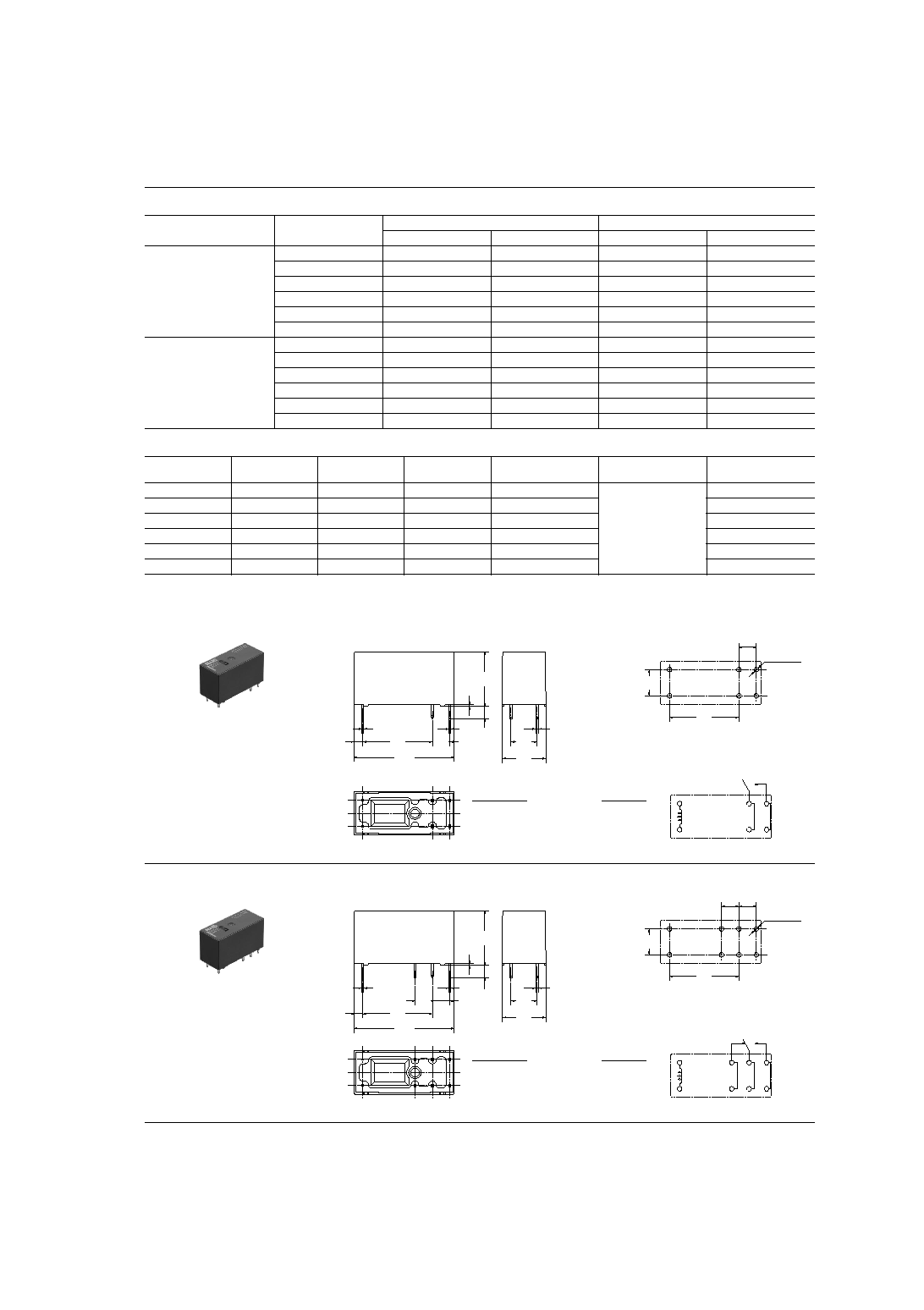
16A Low Profile Power Relay
15.7
.618
12.5
.492
28.8
1.134
FEATURES
1. Low profile size: Height 15.7 mm
28.8 (L)
◊
12.5 (W)
◊
15.7(H) mm
1.134
(L)
◊
.492 (W)
◊
.618(H) inch
2. High insulation resistance
Creepage distance and clearances
between contact and coil: Min. 10 mm
3. UL coil insulation class B (85∞C
185∞F
) or class F (105∞C
221∞F
).
4. Pb free and Cd free
5. Low operating power
∑ Nominal operating power: 400mW
6. Conforms to the various safety
standards:
∑ UL/CSA, VDE approved.
SPECIFICATIONS
Contact
Coil
Remarks
*
Specifications will vary with foreign standards certification ratings.
*
1
Measurement at same location as "Initial breakdown voltage" section.
*
2
Detection current: 10mA
*
3
Wave is standard shock voltage of
±
1.2
◊
50
µ
s according to JEC-212-1981
*
4
Excluding contact bounce time.
*
5
Half-wave pulse of sine wave: 0.8 ms; detection time: 10
µ
s
*
6
Half-wave pulse of sine wave: 6 ms
*
7
Detection time: 10
µ
s
*
8
Refer to 5. Conditions for operation, transport and storage mentioned in
AMBIENT ENVIRONMENT (Page 24).
*
9
Class F type is ambient temperature 105∞C
221∞F
.
*
10
Electrical life was evaluated with the breathing hole open.
Characteristics
Arrangement
1 Form A, 1 Form C
Initial contact resistance, max.
(By voltage drop 6 V DC 1 A)
100 m
Contact material
Silver alloy
Rating
(resistive load)
Nominal switching
capacity
16 A 250 V AC
Max. switching power
4,000 V A
Max. switching voltage
440 V AC
Max. switching current
16 A
Expected life
(min. operations)
Mechanical
(at 180 cpm)
1
◊
10
7
Electrical (at 20 cpm)*
10
(Resistive load)
N.O.: 10
5
N.C.: 5
◊
10
4
Nominal operating power
400 mW
Max. operating speed (at rated load)
20 cpm
Initial insulation resistance*
1
Min. 1,000 M
(at 500 V DC)
Initial
breakdown
voltage*
2
Between open contacts
1,000 Vrms for 1 min.
Between contacts and
coil
5,000 Vrms for 1 min.
Initial surge voltage between contact
and coil*
3
Min. 10,000 V
Operate time*
4
(at nominal voltage)
Max. 15ms (at 20
∞
C
68
∞
F
)
Release time (with diode)*
4
(at nominal voltage)
Max. 5ms (at 20
∞
C
68
∞
F
)
Temperature rise (at nominal voltage)
Max. 55
∞
C
(resistance method, contact
current 16 A, 20
∞
C
68
∞
F
)
Shock resistance
Functional*
5
Min. 100 m/s
2
{10 G}
Destructive*
6
Min. 1,000 m/s
2
{100 G}
Vibration resistance
Functional*
7
10 to 55Hz
at double amplitude of
1.5mm (NO), 0.82mm (NC)
Destructive
10 to 55Hz
at double amplitude of 1.5mm
Conditions for
operation, transport
and storage*
8
(Not freezing and
condensing at low
temperature)
Ambient temp.
≠40
∞
C to +85
∞
C
≠40
∞
F to +185
∞
F
(Class B)*
9
Humidity
5 to 85% R.H.
Unit weight
Approx. 12 g
.42 oz
TYPICAL APPLICATIONS
∑ HVAC
∑ Oven ranges
∑ Refrigerators
ORDERING INFORMATION
A
Ex.
LZ
1
2
B
12
W
UL/CSA approved type is standard.
Notes: 1. Tube packing: Inner carton: 20pcs.; Case: 800pcs.
2. Carton packing: Inner carton: 100pcs.; Case: 500pcs.
3. Carton packing symbol "W" is not marked on the relay.
LZ
1: 1 Form C
2: 1 Form A
1: Flux-resistant type
2: Sealed type
B:
F:
Class B insulation
Class F insulation
05: 5 18: 18
09: 9 24: 24
12: 12 48: 48
Product name
Contact arrangement
Protective construction
Coil insulation class
Coil voltage, V DC
Nil: Tube packing
W: Carton packing
Packing style
VDE