106
TESTING
VDE
(Reinforced type)
(Standard type)
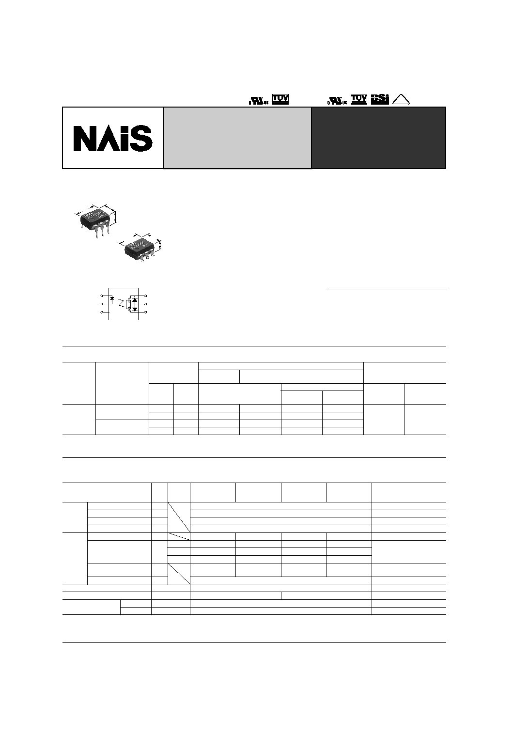
1
2
3
6
5
4
General use and economy type.
DIP (1 Form A) 6-pin type.
Reinforced insulation 5,000V
type.
mm
inch
8.8
.346
6.4
.252
3.9
.154
8.8
.346
6.4
.252
3.6
.142
FEATURES
1. Controls low-level analog signals
PhotoMOS relays feature extremely low
closed-circuit offset voltage to enable
control of low-level analog signals without
distortion.
2. Control with low-level input signals
3. Controls various types of loads such
as relays, motors, lamps and
solenoids.
4. Optical coupling for extremely high
isolation
Unlike mechanical relays, the PhotoMOS
relay combines LED and optoelectronic
device to transfer signals using light for
extremely high isolation.
5. Eliminates the need for a counter
electromotive force protection diode in
the drive circuits on the input side
6. Stable on resistance
7. Low-level off state leakage current
8. Eliminates the need for a power
supply to drive the power MOSFET
A power supply used to drive the power
MOSFET is unnecessary because of the
built-in optoelectronic device. This results
in easy circuit design and small PC board
area.
9. Low thermal electromotive force
(Approx. 1
µ
V)
TYPICAL APPLICATIONS
∑ High-speed inspection machines
∑ Telephone equipment
∑ Data communication equipment
∑ Computer
TYPES
*Indicate the peak AC and DC values.
Note: For space reasons, the SMD terminal shape indicator "A" and the package type indicator "X" and "Z" are omitted from the seal.
Type
I/O isolation
Output rating*
Part No.
Packing quantity
Through hole
terminal
Surface-mount terminal
Load
voltage
Load
current
Tube packing style
Tape and reel packing style
Tube
Tape and reel
Picked from the
1/2/3-pin side
Picked from the
4/5/6-pin side
AC/DC
Standard 1,500 V AC
350 V
130 mA
AQV210E
AQV210EA
AQV210EAX
AQV210EAZ
1 tube contains
50 pcs.
1 batch contains
500 pcs.
1,000 pcs.
400 V
120 mA
AQV214E
AQV214EA
AQV214EAX
AQV214EAZ
Reinforced 5,000 V
350 V
130 mA
AQV210EH
AQV210EHA
AQV210EHAX
AQV210EHAZ
400 V
120 mA
AQV214EH
AQV214EHA
AQV214EHAX
AQV214EHAZ
RATING
1. Absolute maximum ratings (Ambient temperature: 25
∞
C
77
∞
F
)
Item
Sym-
bol
Type of
connec-
tion
AQV210E(A)
AQV214E(A)
AQV210EH(A)
AQV214EH(A)
Remarks
Input
LED forward current
I
F
50 mA
LED reverse voltage
V
R
5 V
Peak forward current
I
FP
1 A
f = 100 Hz, Duty factor = 0.1%
Power dissipation
P
in
75 mW
Output
Load voltage (peak AC)
V
L
350 V
400 V
350 V
400 V
Continuous load current
I
L
A
0.13 A
0.12 A
0.13 A
0.12 A
A connection: Peak AC, DC;
B, C connection: DC
B
0.15 A
0.13 A
0.15 A
0.13 A
C
0.17 A
0.15 A
0.17 A
0.15 A
Peak load current
I
peak
0.4 A
0.3 A
0.4 A
0.3 A
A connection: 100 ms (1 shot),
V
L
=DC
Power dissipation
P
out
500 mW
Total power dissipation
P
T
550 mW
I/O isolation voltage
V
iso
1,500 V AC
5,000 V AC
Temperature limits
Operating
T
opr
≠40
∞
C to +85
∞
C
≠40
∞
F to +185
∞
F
Non-condensing at low temp.
Storage
T
stg
≠40
∞
C to +100
∞
C
≠40
∞
F to +212
∞
F
GU-E PhotoMOS
(AQV210E,
AQV21
EH)
GU-E PhotoMOS (AQV210E, AQV21
EH)
107
2. Electrical characteristics (Ambient temperature: 25
∞
C
77
∞
F
)
For type of connection, see page 34.
*Turn on/Turn off time
** Recommendable LED forward current
Standard type: 5 mA
Reinforced type: 5 to 10 mA
I
For Dimensions, see Page 29.
I
For Schematic and Wiring Diagrams, see Page 34.
I
For Cautions for Use, see Page 38.
Item
Symbol
Type of
connec-
tion
AQV210E(A)
AQV214E(A)
AQV210EH(A)
AQV214EH(A)
Condition
Input
LED operate current
Typical
I
Fon
--
1.1 mA
1.6 mA
I
L
= Max.
Maximum
3 mA
LED turn off current
Minimum
I
Foff
--
0.3 mA
0.4 mA
I
L
= Max.
Typical
1.0 mA
1.5 mA
LED dropout voltage
Typical
V
F
--
1.25 V (1.14 V at I
F
= 5 mA)
I
F
= 50 mA
Maximum
1.5 V
Output
On resistance
Typical
R
on
A
23
30
23
30
I
F
= 5 mA
I
L
= Max.
Within 1 s on time
Maximum
35
50
35
50
Typical
R
on
B
11.5
22.5
11.5
22.5
I
F
= 5 mA
I
L
= Max.
Within 1 s on time
Maximum
17.5
25
17.5
25
Typical
R
on
C
6.0
11.3
6.0
11.3
I
F
= 5 mA
I
L
= Max.
Within 1 s on time
Maximum
8.8
12.5
8.8
12.5
Output capacitance
Typical
C
out
A
45 pF
I
F
= 0 mA
V
B
= 0 V
f = 1 MHz
Off state leakage
current
Maximum
--
--
1
µ
A
I
F
= 0 mA
V
L
= Max.
Transfer
characteristics
Switching
speed
Turn on
time*
Typical
T
on
--
0.5 ms
0.7 ms
I
F
= 0 mA
5 mA**
l
L
= Max.
Maximum
2.0 ms
Turn off
time*
Typical
T
off
--
0.05 ms
I
F
= 0 mA
5 mA
I
L
= Max.
Maximum
1.0 ms
I/O capacitance
Typical
C
iso
--
0.8 pF
f = 1 MHz
V
B
= 0 V
Maximum
1.5 pF
Initial I/O isolation
resistance
Minimum
R
iso
--
1,000 M
500 V DC
Ton
Input
Output
10%
90%
Toff
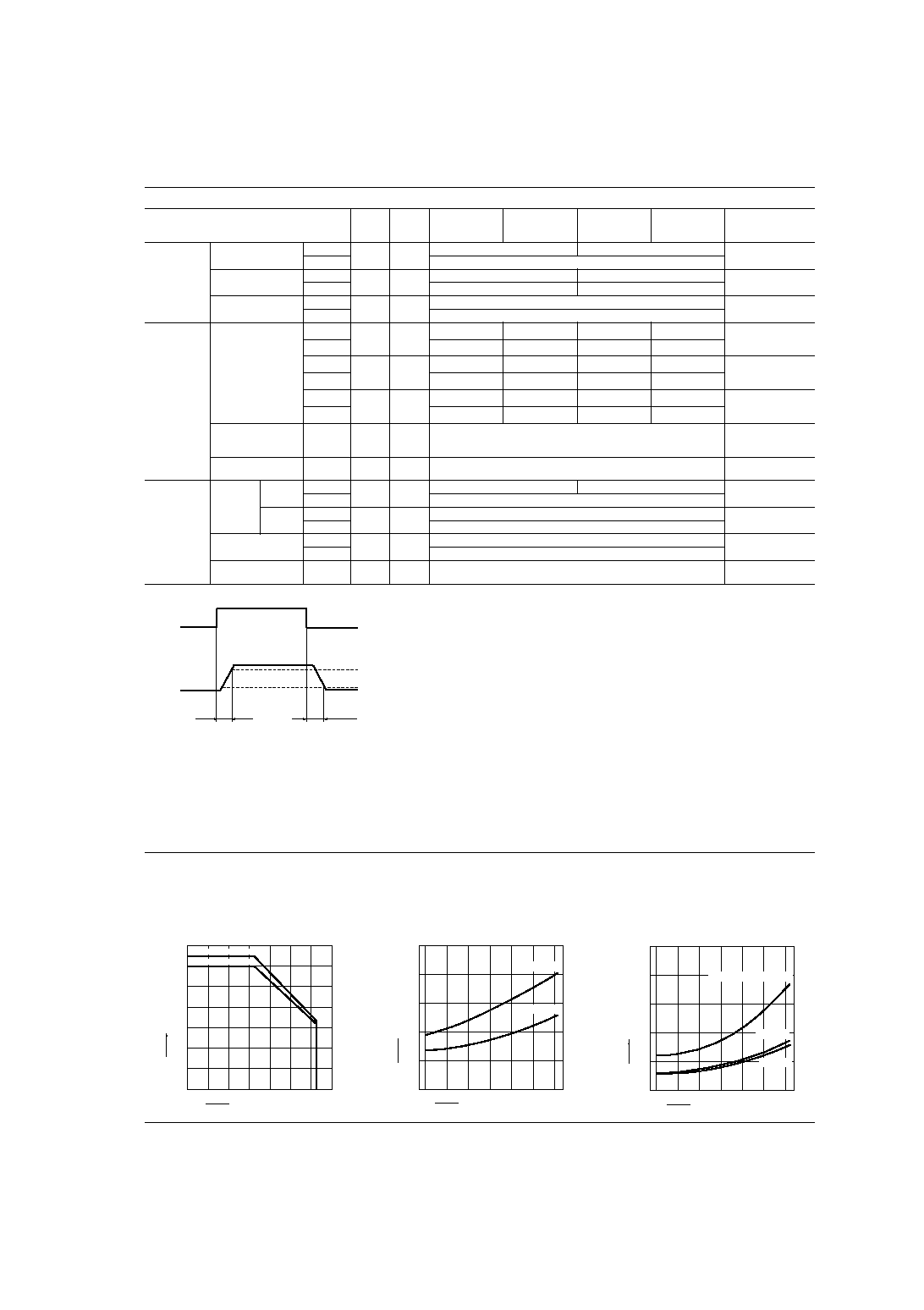
REFERENCE DATA
1. Load current vs. ambient temperature
characteristics
Allowable ambient temperature: ≠40
∞
C to +85
∞
C
≠40
∞
F to +185
∞
F
Type of connection:A
2. On resistance vs. ambient temperature
characteristics
Measured portion: between terminals 4 and 6;
LED current: 5 mA; Load voltage: Max. (DC);
Continuous load current: Max. (DC)
3. Turn on time vs. ambient temperature
characteristics
LED current: 5 mA;
Load voltage: Max. (DC);
Continuous load current: Max. (DC)
0
40
60
80
100
140
120
0
20
40
60
≠20
80
100
≠40
AQV210E (H)
Ambient temperature,
∞C
20
AQV214E (H)
Load current, mA
85
0
10
20
30
40
≠40
50
0
≠20
20
40
60
80
AQV210E (H)
AQV214E (H)
85
Ambient temperature,
∞C
On resistance,
0
0.8
1.2
≠40
2.0
0
≠20
20
40
60
80
0.4
1.6
85
AQV210EH, AQV214EH
AQV214E
AQV210E
Ambient temperature,
∞C
Turn on time, ms
GU-E PhotoMOS (AQV210E, AQV21
EH)
108
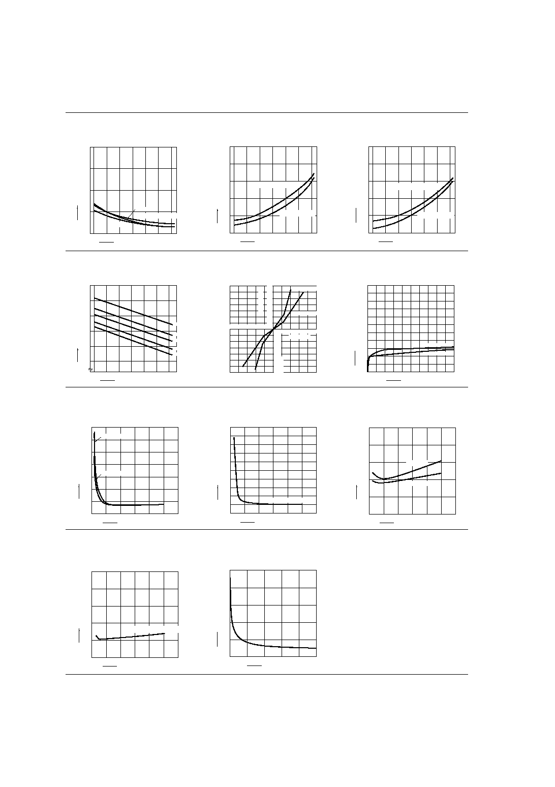
4. Turn off time vs. ambient temperature
characteristics
LED current: 5 mA; Load voltage: Max. (DC);
Continuous load current: Max. (DC)
5. LED operate current vs. ambient
temperature characteristics
Load voltage: Max. (DC);
Continuous load current: Max. (DC)
6. LED turn off current vs. ambient temperature
characteristics
Load voltage: Max. (DC);
Continuous load current: Max. (DC)
0
0.1
0.2
0.3
0.4
≠40
0
≠20
20
40
60
80
AQV210E
AQV214E
AQV210EH, AQV214EH
85
Ambient temperature,
∞C
Turn off time, ms
0
1
2
3
4
≠40
5
0
≠20
20
40
60
8085
AQV210E,AQV214E
AQV210EH, AQV214EH
Ambient temperature,
∞C
LED operate current, mA
0
1
2
3
4
≠40
5
0
≠20
20
40
60
8085
AQV210E,AQV214E
AQV210EH, AQV214EH
Ambient temperature,
∞C
LED turn off current, mA
7. LED dropout voltage vs. ambient
temperature characteristics
Sample: All types
LED current: 5 to 50 mA
8. Current vs. voltage characteristics of output
at MOS portion
Measured portion: between terminals 4 and 6;
Ambient temperature: 25
∞
C
77
∞
F
9. Off state leakage current vs. load voltage
characteristics
Measured portion: between terminals 4 and 6;
Ambient temperature: 25
∞
C
77
∞
F
0
1.0
1.1
1.2
1.3
≠40
0
≠20
20
40
60
80
1.4
50mA
30mA
20mA
10mA
5mA
1.5
85
Ambient temperature,
∞C
LED dropout voltage, V
5
3
1
≠5
≠3
≠1
≠140
≠80
≠20
140
80
20
40
60
100
120
≠40
≠60
≠100
≠120
≠2
≠4
2
4
AQV210E(H)
AQV214E(H)
Voltage, V
Curremt, mA
0
60
100
10
≠3
≠6
10
10
≠9
10
≠12
AQV214E(H)
20
40
80
AQV210E(H)
Load voltage, V
Off state leakage current, A
10-(1). Turn on time vs. LED forward current
characteristics
Measured portion: between terminals 4 and 6;
Load voltage: Max. (DC); Continuous load current:
Max. (DC); Ambient temperature: 25
∞
C
77
∞
F
10-(2). Turn on time vs. LED forward current
characteristics
Measured portion: between terminals 4 and 6;
Load voltage: Max. (DC); Continuous load current:
Max. (DC); Ambient temperature: 25
∞
C
77
∞
F
11-(1). Turn off time vs. LED forward current
characteristics
Measured portion: between terminals 4 and 6;
Load voltage: Max. (DC); Continuous load current:
Max. (DC); Ambient temperature: 25
∞
C
77
∞
F
0
0.2
0.4
0.6
0.8
1.4
1.0
10
20
30
40
50
60
AQV214E
AQV210E
1.2
LED forward current, mA
Turn on time, ms
0
0.5
1.0
2.5
1.5
10
20
30
40
50
60
2.0
AQV210EH, AQV214EH
LED forward current, mA
Turn on time, ms
0
0.02
0.04
0.08
0.06
10
20
30
40
0.10
50
AQV210E
AQV214E
LED forward current, mA
Turn off time, ms
11-(2). Turn off time vs. LED forward current
characteristics
Measured portion: between terminals 4 and 6;
Load voltage: Max. (DC); Continuous load current:
Max. (DC); Ambient temperature: 25
∞
C
77
∞
F
12. Output capacitance vs. applied voltage
characteristics
Measured portion: between terminals 4 and 6;
Frequency: 1 MHz;
Ambient temperature: 25
∞
C
77
∞
F
0
0.05
0.10
0.20
0.15
10
20
30
40
0.25
50
AQV210EH, AQV214EH
LED forward current, mA
Turn off time, ms
0
10
20
50
10
20
30
40
50
30
40
0
Applied voltage, V
Output capacitance, pF