 | –≠–ª–µ–∫—Ç—Ä–æ–Ω–Ω—ã–π –∫–æ–º–ø–æ–Ω–µ–Ω—Ç: AQY210HL | –°–∫–∞—á–∞—Ç—å:  PDF PDF  ZIP ZIP |
GU PhotoMOS (AQY210HL)
97
1
2
4
3
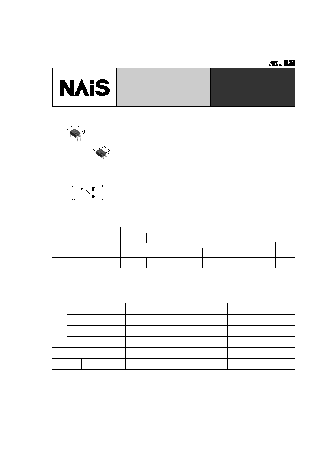
GU PhotoMOS
(AQY210HL)
Current Limit Function.
DIP(1 Form A) 4-pin type.
Reinforced insulation
5,000V type.
3.2
.126
6.4
.252
4.78
.188
2.9
.114
6.4
.252
4.78
.188
FEATURES
1. Current Limit Function
To control an over current from flowing,
the current limit function has been
realized. It keeps an output current at a
constant value when the current reaches
a specified current limit value.
2. Enhancing the capability of surge
resistance between output terminals
The current limit function controls the ON
time surge current to enhance the
capability of surge resistance between
output terminals.
3. Reinforced insulation 5,000 V type
More than 0.4 mm internal insulation
distance between inputs and outputs.
Con-forms to EN41003, EN60950
(reinforced insulation).
4. Compact 4-pin DIP size
The device comes in a compact (W)6.4
◊
(L)4.78
◊
(H) 3.2mm
(W).252
◊
(L).188
◊
(H).126inch
, 4-pin DIP size
5. Controls low-level analog signals
PhotoMOS relays feature extremely low
closed-circuit offset voltage to enable
control of low-level analog signals without
distortion.
6. High sensitivity, low ON resistance
7. Low-level off state leakage current
TYPICAL APPLICATIONS
∑ Telephone equipment
∑ Modem
TYPES
*Indicate the peak AC and DC values.
Note: For space reasons, the initial letters of the product number "AQY", the SMD terminal shape indicator "A" and the package type indicator "X" and "Z" are omitted from
the seal.
Type
I/O isola-
tion voltage
Output rating*
Part No.
Packing quantity
Through hole
terminal
Surface-mount terminal
Load
voltage
Load
current
Tube packing style
Tape and reel packing style
Tube
Tape and
reel
Picked from the
1/2-pin side
Picked from the
3/4-pin side
AC/DC
type
Reinforced
5,000 V
350 V
120 mA
AQY210HL
AQY210HLA
AQY210HLAX
AQY210HLAZ
1 tube contains 100 pcs.
1 batch contains 1,000 pcs.
1,000 pcs.
RATING
1. Absolute maximum ratings (Ambient temperature: 25
∞
C
77
∞
F
)
Item
Symbol
AQY210HL(A)
Remarks
Input
LED forward current
I
F
50 mA
LED reverse voltage
V
R
5 V
Peak forward current
I
FP
1 A
f = 100 Hz, Duty factor = 0.1%
Power dissipation
P
in
75 mW
Output
Load voltage (peak AC)
V
L
350 V
Continuous load current
I
L
0.12 A
Power dissipation
P
out
500 mW
Total power dissipation
P
T
550 mW
I/O isolatiom voltage
V
iso
5,000 V AC
Temperature
limits
Operating
T
opr
≠40
∞
C to +85
∞
C
≠40
∞
F to +185
∞
F
Non-condensing at low temperatures
Storage
T
stg
≠40
∞
C to +100
∞
C
≠40
∞
F to +212
∞
F
mm
inch
TESTING
GU PhotoMOS (AQY210HL)
98
2. Electrical characteristics (Ambient temperature: 25
∞
C
77
∞
F
)
Note: Recommendable LED forward current I
F
= 5 to 10 mA. For type of connection, see page 34.
*Turn on/Turn off time
Item
Symbol
AQY210HL(A)
Condition
Input
LED operate
current
Typical
I
Fon
1.2 mA
I
L
= Max.
Maximum
3.0 mA
LED turn off
current
Minimum
I
Foff
0.4 mA
I
L
= Max.
Typical
1.1 mA
LED dropout
voltage
Minimum
V
F
1.25 (1.14 V at I
F
= 5 mA)
I
F
= 50 mA
Typical
1.5 V
Output
On resistance
Typical
R
on
20
I
F
= 5 mA
I
L
= Max.
Within 1 s on time
Maximum
25
Off state leak-
age current
Maximum
I
Leak
1
µ
A
I
F
= 0 mA
V
L
= Max.
Current limit
Typical
--
0.18 A
I
F
= 5 mA
Transfer char-
acteristics
Turn on time*
Typical
T
on
0.5 ms
I
F
= 5 mA
I
L
= Max.
Maximum
2.0 ms
Turn off time*
Typical
T
off
0.08 ms
I
F
= 5 mA
I
L
= Max.
Maximum
1.0 ms
I/O capacitance
Typical
C
iso
0.8 pF
f = 1 MHz
V
B
= 0 V
Maximum
1.5 pF
Initial I/O isola-
tion resistance
Minimum
R
iso
1,000 M
500 V DC
Ton
Input
Output
10%
90%
Toff
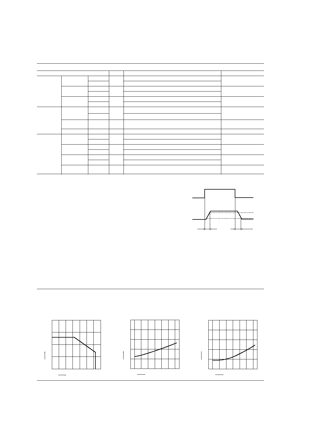
REFERENCE DATA
1. Load current vs. ambient temperature
characteristics
Allowable ambient temperature: ≠40
∞
C to +85
∞
C
≠40
∞
F to +185
∞
F
2. On resistance vs. ambient temperature
characteristics
Measured portion: between terminals 3 and 4;
LED current: 5 mA; Load voltage: Max. (DC)
Continuous load current: Max.(DC)
3. Turn on time vs. ambient temperature
characteristics
LED current: 5 mA; Load voltage: Max.(DC);
Continuous load current: Max.(DC)
Ambient temperature,
∞C
Load current, mA
0
200
150
100
50
0
20
40
60
80 85 100
≠20
≠40
On resistance,
Ambient temperature,
∞C
0
10
20
30
40
≠40
≠20
50
0
20
40
60
80 85
Ambient temperature,
∞C
Turn on time, ms
0
0.5
1
1.5
2
≠40
≠20
2.5
0
20
40
60
80 85
I
For Dimensions, see Page 29.
I
For Schematic and Wiring Diagrams, see Page 34.
I
For Cautions for Use, see Page 38.

GU PhotoMOS (AQY210HL)
99
4. Turn off time vs. ambient temperature
characteristics
LED current: 5 mA; Load voltage: Max.(DC);
Continuous load current: Max.(DC)
5. LED operate current vs. ambient
temperature characteristics
Load voltage: Max.(DC);
Continuous load current: Max.(DC)
6. LED turn off current vs. ambient temperature
characteristics
Load voltage: Max.(DC);
Continuous load current: Max.(DC)
Ambient temperature,
∞C
Turn off time, ms
0
0.05
0.1
0.15
0.2
≠40
≠20
0.25
0
20
40
60
80 85
Ambient temperature,
∞C
LED operate current, mA
0
1
2
3
4
≠40 ≠20
5
0
20
40
60
80 85
Ambient temperature,
∞C
LED turn off current, mA
0
1
2
3
4
≠40 ≠20
5
0
20
40
60
80 85
7. LED dropout voltage vs. ambient
temperature characteristics
LED current: 5 to 50 mA
8. Current vs. voltage characteristics of output
at MOS portion
Measured portion: between terminals 3 and 4;
Ambient temperature: 25
∞
C
77
∞
F
9. Off state leakage current vs. load voltage
characteristics
Measured portion: between terminals 3 and 4;
Ambient temperature: 25
∞
C
77
∞
F
0
≠40 ≠20
20
40
60
80 85
Ambient temperature,
∞C
LED dropout voltage, V
1.5
1.4
1.3
1.2
1.1
1.0
0
50mA
30mA
20mA
10mA
5mA
5
3
1
≠5
≠3
140
120
60
40
20
≠20
≠40
≠60
≠80
≠100
≠120
≠140
100
80
≠2
≠4
2
4
≠1
Voltage, V
Current, mA
Load voltage, V
Off state leakage current, A
0
60
100
10
≠3
10
≠6
10
≠9
10
≠12
20
40
80
10. Turn on time vs. LED forward current
characteristics
Measured portion: between terminals 3 and 4;
Load voltage: Max.(DC); Continuous load current:
Max.(DC); Ambient temperature: 25
∞
C
77
∞
F
11. Turn off time vs. LED forward current
characteristics
Measured portion: between terminals 3 and 4;
Load voltage: Max.(DC); Continuous load current:
Max.(DC); Ambient temperature: 25
∞
C
77
∞
F
12. Output capacitance vs. applied voltage
characteristics
Measured portion: between terminals 3 and 4;
Frequency: 1 MHz; Ambient temperature: 25
∞
C
77
∞
F
LED forward current, mA
Turn on time, ms
0
0.5
1
1.5
2
3
2.5
10
0
20
30
40
50
60
LED forward current, mA
Turn off time, ms
0
0.05
0.1
10
0
20
30
40
0.2
50
60
0.15
Applied voltage, V
Output capacitance, pF
0
50
40
30
20
10
10
20
30
40
50
0
What is current limit
When a load current reaches the
specified output control current, a current
limit function works against the load
current to keep the current a constant
value.
The current limit circuit built into the
PhotoMOS relay thus controls the
instantaneous load current to effectively
ensure circuit safety.
This safety feature protects circuits
downstream of the PhotoMOS relay
against over-current.
But, if the current-limiting feature is used
longer than the specified time, the
PhotoMOS relay can be destroyed.
Therefore, set the output loss to the max.
rate or less.
∑ Comparison of output voltage and output
current characteristics
V-I Characteristics
Output current
Output voltage