 | –≠–ª–µ–∫—Ç—Ä–æ–Ω–Ω—ã–π –∫–æ–º–ø–æ–Ω–µ–Ω—Ç: HP2-DC12V | –°–∫–∞—á–∞—Ç—å:  PDF PDF  ZIP ZIP |
Document Outline
- ˛ˇ
- ˛ˇ
- ˛ˇ
- ˛ˇ
- ˛ˇ
- ˛ˇ
- ˛ˇ
- ˛ˇ
- ˛ˇ
- ˛ˇ
- ˛ˇ
411
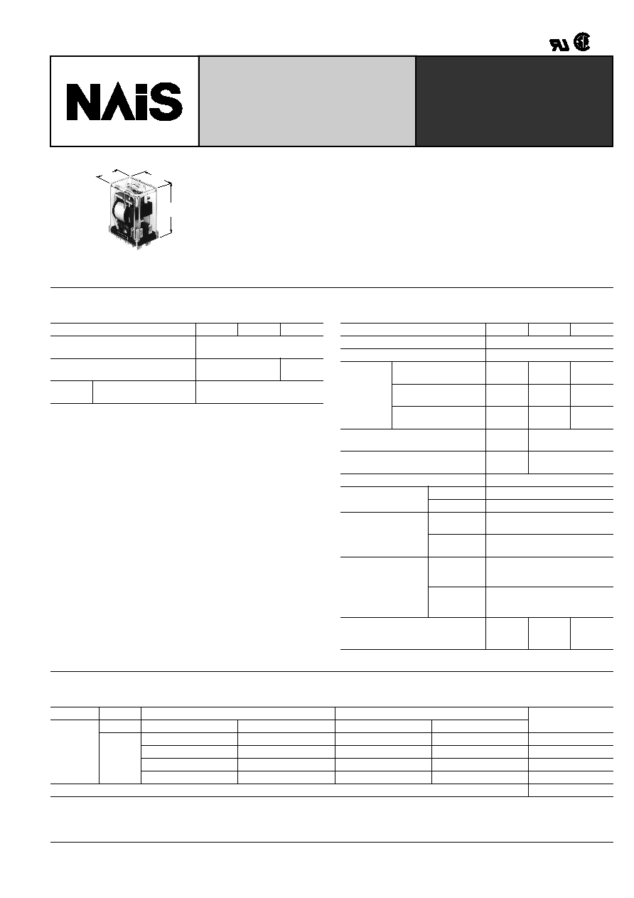
HP-RELAYS
10 AMP POWER RELAY
VDE
2c, 3c
mm
inch
25
.984
36
1.417
44.5
1.752
FEATURES
∑ Interchangeable with existing models
∑ Long life and high reliability
∑ High contact capacity up to 10 A 250 V AC
∑ Available with plug-in/solder and quick-connect terminals
SPECIFICATIONS (at 20
∞
C
68
∞
F
)
Contacts
Remarks
* Specifications will vary with foreign standards certification ratings.
*
1
Measurement at same location as "initial breakdown voltage" section
*
2
Detection current; 10 mA
*
3
Excluding contact bounce time
*
4
Half-wave pulse of sine wave: 11ms; detection time: 10
µ
s
*
5
Half-wave pulse of sine wave: 6ms
*
6
Detection time: 10
µ
s
*
7
Refer to 5. Conditions for operation, transport and storage mentioned in
AMBIENT ENVIRONMENT (Page 61).
Characteristics (at 60 Hz, 20
∞
C
68
∞
F
)
Arrangement
2 Form C 3 Form C 4 Form C
Initial contact resistance, max.
(By voltage drop 6 V DC 1 A)
15 m
Contact material
Silver
Silver
alloy
Rating
Nominal switching
capacity
10 A 250 V AC (resistive)
2 Form C 3 Form C 4 Form C
Maximum operating speed
20 cpm
Initial insulation resistance*
1
more than 100 M
at 500 V DC
Breakdown
voltage*
2
Between open
contacts
1,000
Vrms
2,000
Vrms
1,000
Vrms
Between contact sets
1,500
Vrms
2,000
Vrms
1,500
Vrms
Between contact and
coil
1,500
Vrms
2,000
Vrms
1,500
Vrms
Operate time*
3
(at nominal voltage)
Approx.
15 ms
Approx. 25 ms
Release time (without diode)*
3
(at nominal voltage)
Approx.
15 ms
Approx. 25 ms
Temperature rise
Max. 65
∞
C
Shock resistance
Functional*
4
98 m/s
2
{10 G}
Destructive*
5
980 m/s
2
{100 G}
Vibration resistance
Functional*
6
58.8 m/s
2
{6 G}, 10 to 55 Hz
at 1 mm double amplitude
Destructive
117.6 m/s
2
{12 G}, 10 to 55 Hz
at 2 mm double amplitude
Conditions for opera-
tion, transport and
storage*
7
(Not freezing and
condensing at low
temperature)
Ambient
temp.
≠50
∞
C to +40
∞
C
≠58
∞
F to +104
∞
F
Humidity
5 to 85% R.H.
Unit weight
Approx.
60g
2.12 oz
Approx.
100g
3.53 oz
Approx.
125g
4.41 oz
LIFE DATA
Contact rating and expected life For AC load type
Note: When the electromagnet or exciting coil (Solenoid, etc.) is the load, the value of motor or lamp load is applicable.
Voltage
125 V AC
250 V AC
Expected life
(min. operations)
Electrical
life
Load
Resistive (cos
]
1)
Inductive (cos
]
0.4)
Resistive (cos
]
1)
Inductive (cos
]
0.4)
Current
--
--
10 A
7.5 A
2
◊
10
5
10 A
7.5 A
7.5 A
5 A
5
◊
10
5
5 A
3 A
3 A
2 A
1
◊
10
6
1A
0.7 A
0.6 A
0.4 A
2
◊
10
6
Mechanical life
1
◊
10
7
HP
412
Contact rating and expected life For DC load type
Voltage
24 V DC
125 V DC
Expected life
(min. operations)
Electrical
life
Load
Resistive (cos
]
1)
Inductive (cos
]
0.4)
Resistive (cos
]
1)
Inductive (cos
]
0.4)
Current
--
7 A
--
--
2
◊
10
5
7.5 A
5 A
0.5 A
0.4 A
5
◊
10
5
5 A
3 A
0.3 A
0.2 A
1
◊
10
6
1A
0.6 A
0.1 A
0.06 A
2
◊
10
6
Mechanical life
1
◊
10
7
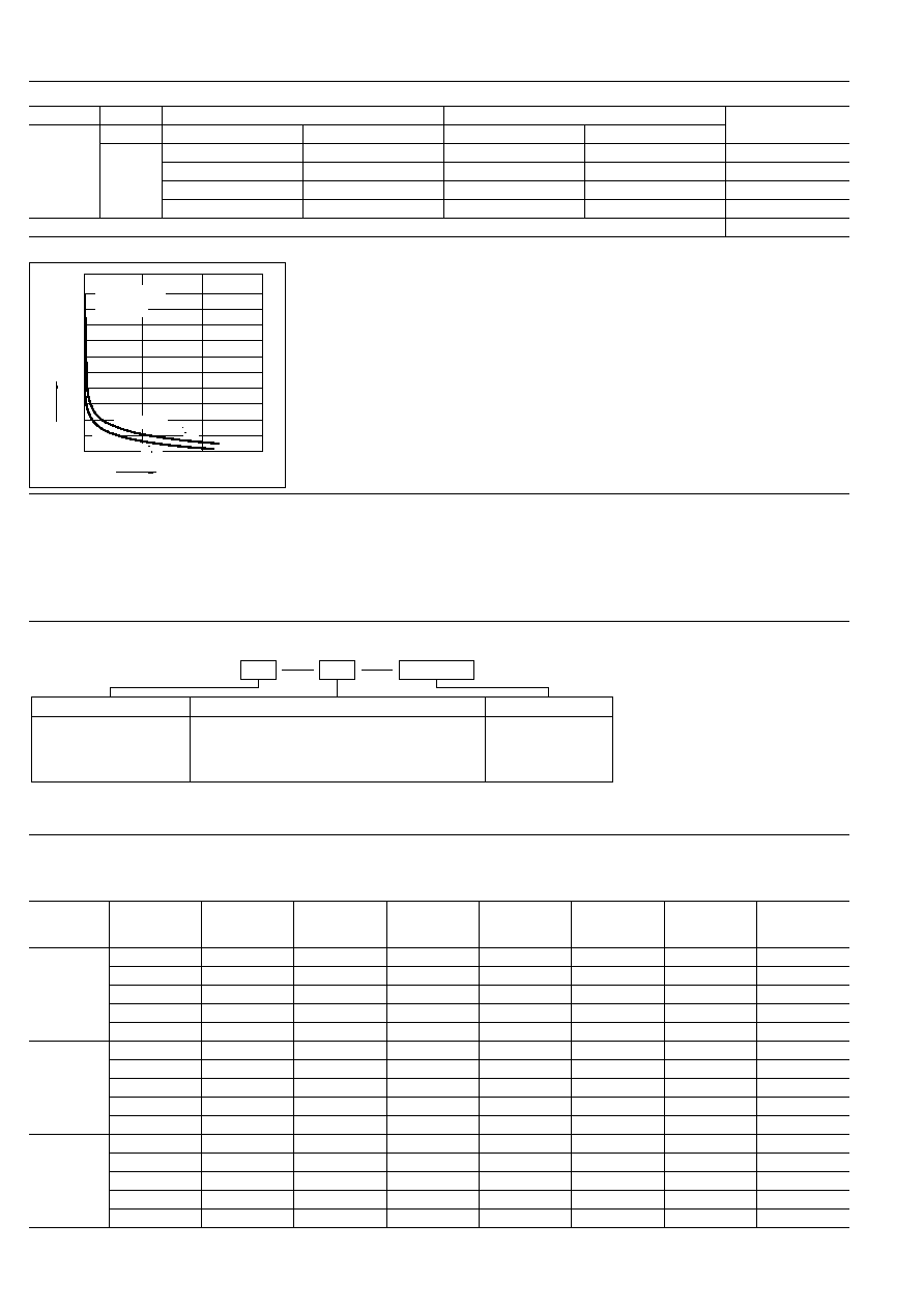
Life curve
Notes:
1. For DC inductive loads, use an arc suppress-
ing circuit.
2. When used under a DC load operating at
high repetition rate with considerable arcing,
corrosion of the contacts and/or the contact
blades is likely to occur. When using the relay
under conditions of high temperature, humidity
or high repetition rate, it is suggested that the
relay cover be removed to facilitate extended
operation.
10
0
100
200
300
400
500
600
700
800
900
1,000
Load current, A
Operations,
◊
10
4
125 V AC cos
= 1
5
2
5
0
V AC
cos
= 1
Mechanical life
more than 10,000,000
operations
TYPICAL APPLICATIONS
HP relays enjoy wide use in various appli-
cations, particularly in automation con-
trols and remote controls.
Applications include:
Industrial machinery
Machine tool
Food processing packing machines
Office equipment
Coin operate devices
Home appliances
Transportation
Communication and measuring devices
Amusement devices
ORDERING INFORMATION
Ex. HP
3
Contact arrangement
2: 2 Form C
3: 3 Form C
4: 4 Form C
(Notes) 1. For UL/CSA or VDE recognized types, add suffix UL/CSA or VDE (HP2-TM type VDE application under way)
2. Standard packing Carton: 50 pcs. Case: 200 pcs.
3. UL/CSA approved type is standard.
Nil: Standard plug-in terminal
M: Direct mounting (3 Form C only)
TM: Top mounting (2 Form C only)
L: Lamp wired, standard plug-in terminal
AC 6, 12, 24, 48,
115, 220, 240 V
DC 6, 12, 24, 48,
110 V
Terminal
Coil voltage
M
AC240V
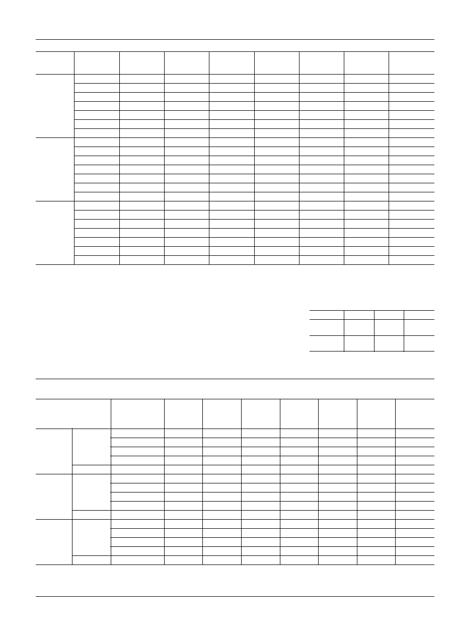
TYPES AND COIL DATA
1. Standard plug-in terminal type (without lamp wired)
DC TYPES at 20
∞
C
68
∞
F
Type
Part No.
Nominal coil
voltage, V DC
Pick-up
voltage,
V DC (max.)
Drop-out
voltage,
V DC (min.)
Max.
allowable
voltage, V DC
Coil
resistance,
(
±
10%)
Nominal coil
current, mA
Nominal
operating
power, W
2 Form C
HP2-DC6V
6
4.8
0.9
6.6
25
240
1.5
HP2-DC12V
12
9.6
1.8
13.2
110
109
1.3
HP2-DC24V
24
19.2
3.6
26.4
440
54.5
1.3
HP2-DC48V
48
38.4
7.2
52.8
1,800
26.7
1.3
HP2-DC110V
110
88
16.5
121
7,300
15.0
1.7
3 Form C
HP3-DC6V
6
4.8
0.9
6.6
24
250
1.5
HP3-DC12V
12
9.6
1.8
13.2
100
120
1.4
HP3-DC24V
24
19.2
3.6
26.4
400
60
1.4
HP3-DC48V
48
38.4
7.2
52.8
1,560
31
1.5
HP3-DC110V
110
88
16.5
121
7,450
14.9
1.6
4 Form C
HP4-DC6V
6
4.8
0.9
6.6
22
273
1.6
HP4-DC12V
12
9.6
1.8
13.2
95
127
1.5
HP4-DC24V
24
19.2
3.6
26.4
380
63
1.5
HP4-DC48V
48
38.4
7.2
52.8
1,500
32
1.5
HP4-DC110V
110
88
16.5
121
7,000
15.7
1.7
HP
413
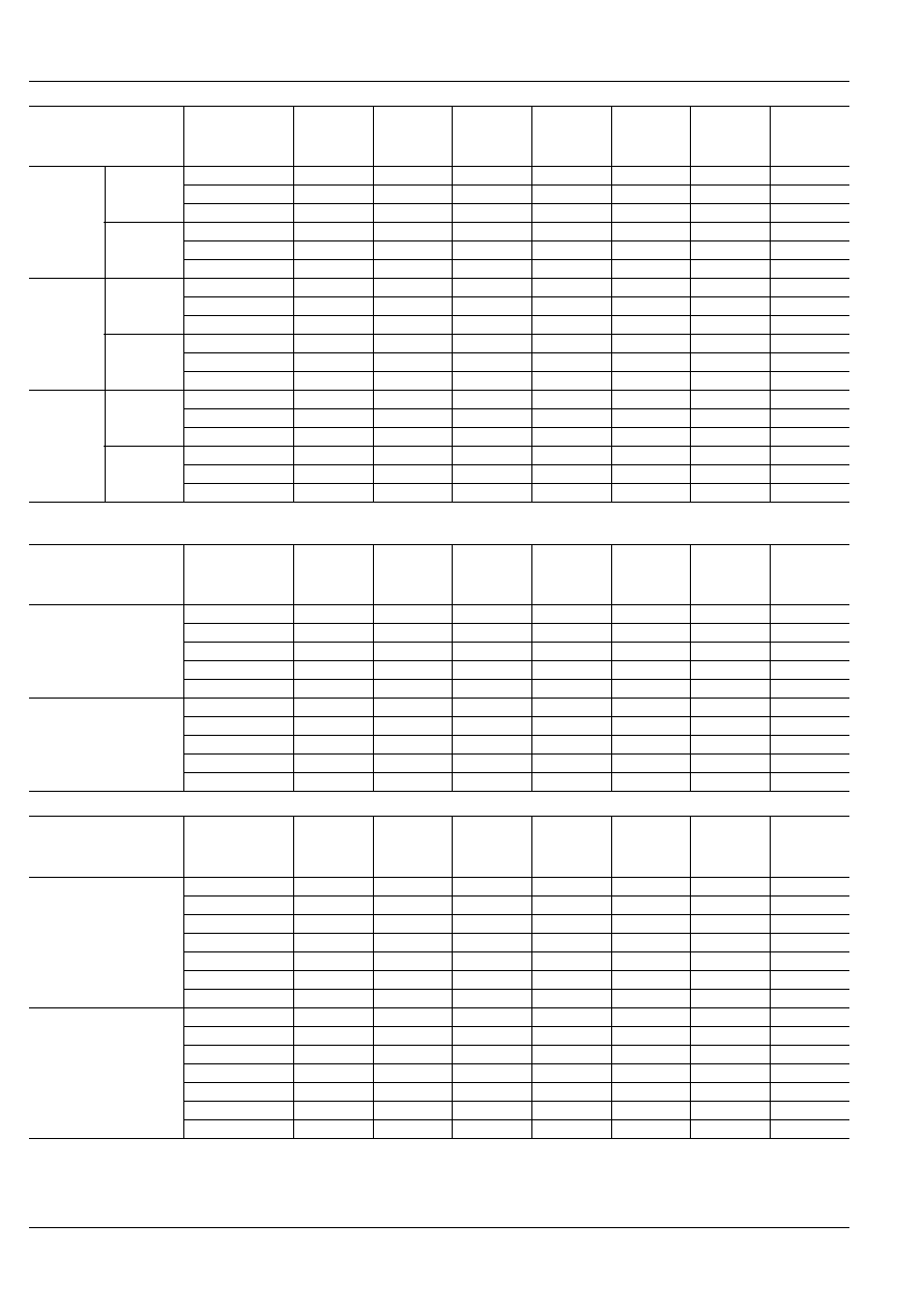
AC TYPE (50/60 Hz) at 60 Hz, 20
∞
C
68
∞
F
Type
Part No.
Nominal coil
voltage, V AC
Pick-up
voltage,
V AC (max.)
Drop-out
voltage,
V AC (min.)
Max.
allowable
voltage, V AC
Inductance,
H
Nominal coil
current, mA
Nominal
operating
power, VA
2 Form C
HP2-AC6V
6
4.8
1.8
6.6
0.049
310
1.9
HP2-AC12V
12
9.6
3.6
13.2
0.190
160
1.9
HP2-AC24V
24
19.2
7.2
26.4
0.776
78
1.9
HP2-AC48V
48
38.4
14.4
52.8
3.106
39
1.9
HP2-AC115V
115
92
34.5
126.5
15.83
18
2.1
HP2-AC220V
220
176
66
242
57.90
9.5
2.1
HP2-AC240V
240
192
72
264
66.26
9.0
2.2
3 Form C
HP3-AC6V
6
4.8
1.8
6.6
0.030
520
3.1
HP3-AC12V
12
9.6
3.6
13.2
0.119
260
3.1
HP3-AC24V
24
19.2
7.2
26.4
0.475
130
3.1
HP3-AC48V
48
38.4
14.4
52.8
1.899
65
3.1
HP3-AC115V
115
92
34.5
126.5
10.36
28.5
3.3
HP3-AC220V
220
176
66
242
39.32
14.2
3.1
HP3-AC240V
240
192
72
264
44.05
13.9
3.3
4 Form C
HP4-AC6V
6
4.8
1.8
6.6
0.019
800
4.8
HP4-AC12V
12
9.6
3.6
13.2
0.077
400
4.8
HP4-AC24V
24
19.2
7.2
26.4
0.309
200
4.8
HP4-AC48V
48
38.4
14.4
52.8
1.292
95
4.6
HP4-AC115V
115
92
34.5
126.5
6.953
42
4.8
HP4-AC220V
220
176
66
242
26.57
21
4.6
HP4-AC240V
240
192
72
264
29.75
20.5
4.9
NOTES
1. The range of coil current for AC relays
is
±
15% (60 Hz). For DC relays it is
±
10% at 20
∞
C,
68
∞
F
.
2. The HP relay will operate in a range
from 80% to 110% of the nominal coil
voltage. It is, however, recommended
that the relay be used in the range of
85% to 110% of the nominal coil volt-
age, with the temporary voltage varia-
tion taken into consideration.
3. When the operating voltage of AC re-
lays drops below 80% of the nominal
coil voltage, the relay will generate a
considerable amount of heat which is
not recommended for maximum effi-
ciency.
4. The coil resistance of DC types is the
measured value of the coil at a temper-
ature of 20
∞
C
68
∞
F
. If the coil tempera-
ture changes by
±
1
∞
C, the measured
value of the coil resistance should be
increased or decreased by 0.4%.
5. For applications from 220 V to 240 V
DC, connect a resistor in series with
the relay coil. See chart for resistor val-
ues.
Voltage
2 Form C 3 Form C 4 Form C
220 V DC
7.3 k
(5 W)
7.45 k
(5 W)
7 k
(5 W)
240 V DC
8.7 k
(5 W)
8.8 k
(5 W)
8.3 k
(5 W)
2. Standard plug-in terminal type (with lamp wired)
DC TYPES at 20
∞
C
68
∞
F
Type
Part No.
Nominal coil
voltage,
V DC
Pick-up
voltage,
V DC (max.)
Drop-out
voltage,
V DC (min.)
Max.
allowable
voltage,
V DC
Coil
resistance,
(
±
10%)
Nominal coil
current,
mA
Nominal
operating
power,
W
2 Form C
LED
HP2-L-DC6V
6
4.8
0.9
6.6
25
240
1.5
HP2-L-DC12V
12
9.6
1.8
13.2
110
109
1.3
HP2-L-DC24V
24
19.2
3.6
26.4
440
54.5
1.3
HP2-L-DC48V
48
38.4
7.2
52.8
1,800
26.7
1.3
Neon lamp
HP2-L-DC110V
110
88
16.5
121
7,300
15.0
1.7
3 Form C
LED
HP3-L-DC6V
6
4.8
0.9
6.6
24
250
1.5
HP3-L-DC12V
12
9.6
1.8
13.2
100
120
1.4
HP3-L-DC24V
24
19.2
3.6
26.4
400
60
1.4
HP3-L-DC48V
48
38.4
7.2
52.8
1,560
31
1.5
Neon lamp
HP3-L-DC110V
110
88
16.5
121
7,450
14.9
1.6
4 Form C
LED
HP4-L-DC6V
6
4.8
0.9
6.6
22
273
1.6
HP4-L-DC12V
12
9.6
1.8
13.2
95
127
1.5
HP4-L-DC24V
24
19.2
3.6
26.4
380
63
1.5
HP4-L-DC48V
48
38.4
7.2
52.8
1,500
32
1.5
Neon lamp
HP4-L-DC110V
110
88
16.5
121
7,000
15.7
1.7
HP
414
AC TYPE (50/60 Hz) at 60 Hz, 20
∞
C
68
∞
F
3. Top Mounting (TM) and direct mounting (M) type
DC TYPES at 20
∞
C
68
∞
F
AC TYPE (50/60 Hz) at 60 Hz, 20
∞
C
68
∞
F
Type
Part No.
Nominal coil
voltage,
V AC
Pick-up
voltage,
V AC (max.)
Drop-out
voltage,
V AC (min.)
Max.
allowable
voltage,
V AC
Inductance,
H
Nominal coil
current,
mA
Nominal
operating
power,
VA
2 Form C
LED
HP2-L-AC6V
6
4.8
1.8
6.6
0.049
310
1.9
HP2-L-AC12V
12
9.6
3.6
13.2
0.190
160
1.9
HP2-L-AC24V
24
19.2
7.2
26.4
0.776
78
1.9
Neon lamp
HP2-L-AC115V
115
92
34.5
126.5
15.83
18
2.1
HP2-L-AC220V
220
176
66
242
57.90
9.5
2.1
HP2-L-AC240V
240
192
72
264
66.26
9.0
2.2
3 Form C
LED
HP3-L-AC6V
6
4.8
1.8
6.6
0.030
520
3.1
HP3-L-AC12V
12
9.6
3.6
13.2
0.119
260
3.1
HP3-L-AC24V
24
19.2
7.2
26.4
0.475
130
3.1
Neon lamp
HP3-L-AC115V
115
92
34.5
126.5
10.36
28.5
3.3
HP3-L-AC220V
220
176
66
242
39.32
14.2
3.1
HP3-L-AC240V
240
192
72
264
44.05
13.9
3.3
4 Form C
LED
HP4-L-AC6V
6
4.8
1.8
6.6
0.019
800
4.8
HP4-L-AC12V
12
9.6
3.6
13.2
0.077
400
4.8
HP4-L-AC24V
24
19.2
7.2
26.4
0.309
200
4.8
Neon lamp
HP4-L-AC115V
115
92
34.5
126.5
6.953
42
4.8
HP4-L-AC220V
220
176
66
242
26.57
21
4.6
HP4-L-AC240V
240
192
72
264
29.75
20.5
4.9
Type
Part No.
Nominal coil
voltage,
V DC
Pick-up
voltage,
V DC (max.)
Drop-out
voltage,
V DC (min.)
Max.
allowable
voltage,
V DC
Coil
resistance,
(
±
10%)
Nominal coil
current,
mA
Nominal
operating
power,
W
2 Form C
Top Mounting Type (TM)
HP2-TM-DC6V
6
4.8
0.9
6.6
25
240
1.5
HP2-TM-DC12V
12
9.6
1.8
13.2
110
109
1.3
HP2-TM-DC24V
24
19.2
3.6
26.4
440
54.5
1.3
HP2-TM-DC48V
48
38.4
7.2
52.8
1,800
26.7
1.3
HP2-TM-DC110V
110
88
16.5
121
7,300
15.0
1.7
3 Form C
Direct Mounting Type (TM)
HP3-M-DC6V
6
4.8
0.9
6.6
24
250
1.5
HP3-M-DC12V
12
9.6
1.8
13.2
100
120
1.4
HP3-M-DC24V
24
19.2
3.6
26.4
400
60
1.4
HP3-M-DC48V
48
38.4
7.2
52.8
1$B!"(J560
31
1.5
HP3-M-DC110V
110
88
16.5
121
7,450
14.9
1.6
Type
Part No.
Nominal coil
voltage,
V AC
Pick-up
voltage,
V AC (max.)
Drop-out
voltage,
V AC (min.)
Max.
allowable
voltage,
V AC
Inductance,
H
Nominal coil
current,
mA
Nominal
operating
power,
VA
2 Form C
Top Mounting Type (TM)
HP2-TM-AC6V
6
4.8
1.8
6.6
0.049
310
1.9
HP2-TM-AC12V
12
9.6
3.6
13.2
0.190
160
1.9
HP2-TM-AC24V
24
19.2
7.2
26.4
0.776
78
1.9
HP2-TM-AC48V
48
38.4
14.4
52.8
3.106
39
1.9
HP2-TM-AC115V
115
92
34.5
126.5
15.83
18
2.1
HP2-TM-AC220V
220
176
66
242
57.90
9.5
2.1
HP2-TM-AC240V
240
192
72
264
66.26
9.0
2.2
3 Form C
Direct Mounting Type (M)
HP3-M-AC6V
6
4.8
1.8
6.6
0.030
520
3.1
HP3-M-AC12V
12
9.6
3.6
13.2
0.119
260
3.1
HP3-M-AC24V
24
19.2
7.2
26.4
0.475
130
3.1
HP3-M-AC48V
48
38.4
14.4
52.8
1.899
65
3.1
HP3-M-AC115V
115
92
34.5
126.5
10.36
28.5
3.3
HP3-M-AC220V
220
176
66
242
39.32
14.2
3.1
HP3-M-AC240V
240
192
72
264
44.05
13.9
3.3
HP
415
4. Direct mounting (with lamp wired) type
DC TYPES
AC TYPE (50/60 Hz) at 60 Hz, 20
∞
C
68
∞
F
Type
Part No.
Nominal coil
voltage,
V DC
Pick-up
voltage,
V DC (max.)
Drop-out
voltage,
V DC (min.)
Max.
allowable
voltage,
V DC
Coil
resistance,
(
±
10%)
Nominal coil
current,
mA
Nominal
operating
power,
W
3 Form C Neon lamp
HP3-ML-DC110V
110
88
16.5
121
7,450
14.9
1.6
Type
Part No.
Nominal coil
voltage,
V AC
Pick-up
voltage,
V AC (max.)
Drop-out
voltage,
V AC (min.)
Max.
allowable
voltage,
V AC
Inductance,
H
Nominal coil
current,
mA
Nominal
operating
power,
VA
3 Form C Neon lamp
HP3-ML-AC115V
115 V
92
34.5
126.5
10.36
28.5
3.3
HP3-ML-AC220V
220 V
176
66
242
39.32
14.2
3.1
HP3-ML-AC240V
240 V
192
72
264
44.05
13.9
3.3
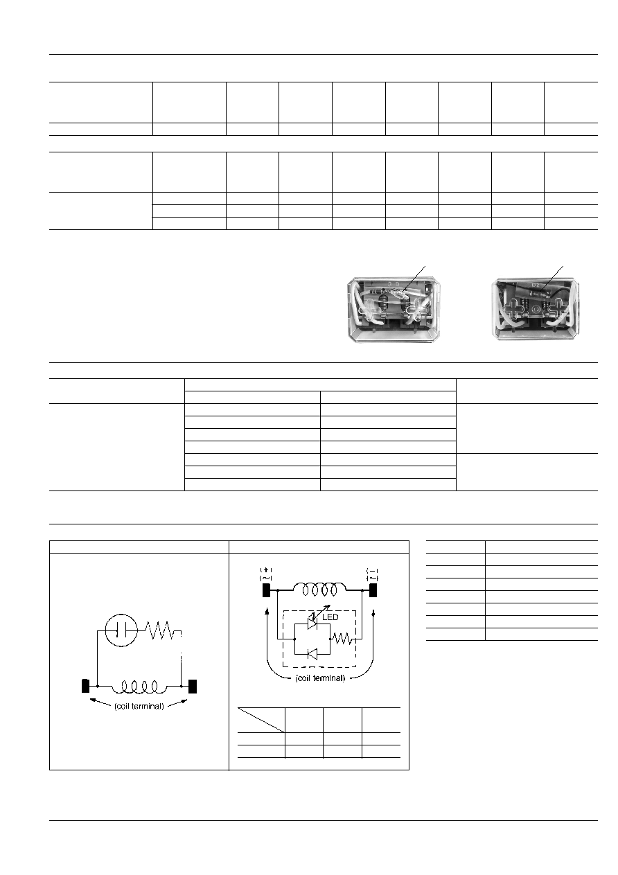
LAMP-WIRED RELAYS
Specifications
Life of neon lamp....continuous: more than 25,000 hours
(more than 3 years)
on/off = 1:
more than 6 years
Life of LED..............continuous: more than 50,000 hours
(more than 5.5 years)
on/off = 1:
more than 100,000 hours
(more than 11 years)
NEON LAMP
LED
Variation
Notes:
1. AC 48 V type is not available for lamp wiring.
Type
Coil Voltage
AC
DC
HP2-L
HP3-L
HP3-ML
HP4-L
6 V
6 V
LED (Light emitting diode)
12 V
12 V
24 V
24 V
--
48 V
115 V
110 V
Neon lamp
220 V
--
240 V
--
Circuit diagrams
Notes:
1. Pay attention to the polarity of coil See circuit diagram (LED type only).
Neon lamp type
LED type
Terminal No.
(DC type)
Type
HP2-L
HP3-L
HP3-ML
HP4-L
Polarity
( + )
7
10
10
( ≠ )
2
2
1
Operating current of LED
Notes:
1. Operating current of relays should be in-
creased by the value of LED operating current.
Please refer the table. Operating current of
neon lamp is approx. 0.3 mA to 0.4 mA.
2. To use the HP relay in the inductive load cir-
cuit, the contact protection circuit is recom-
mended.
Coil Voltage
Operating current of LED
DC 6V
DC 6.4 mA
DC 12V
DC 5.7 mA
DC 24V
DC 4.7 mA
DC 48V
DC 4.5 mA
AC 6V
AC 10.5 mA
AC 12V
AC 9.0 mA
AC 24V
AC 7.7 mA
HP
416
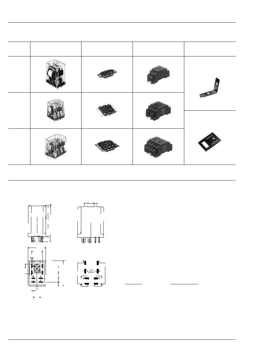
ACCESSORIES
Please refer to "MOUNTING METHODS" for further information.
UL, CSA recognized except BRACKET and INSERTING PLATE.
HP
Relay
Solder terminal socket
for rectangular hold boring
(with hold-down clip)
Screw terminal socket
for DIN rail assembly
(with hold-down clip)
For HP2, HP4
HP2
HP2-SRS
(UL, CSA, VDE)
HP2-SFD
(UL, CSA)
HP-BRACKET
for direct mounting
HP3
HP3-SRS
(UL, CSA, VDE)
HP3-SFD
(UL, CSA, VDE)
HP INSERTION PLATE for P/C
board mounting
HP4
HP4-SRS
(UL, CSA)
HP4-SFD
(UL, CSA)
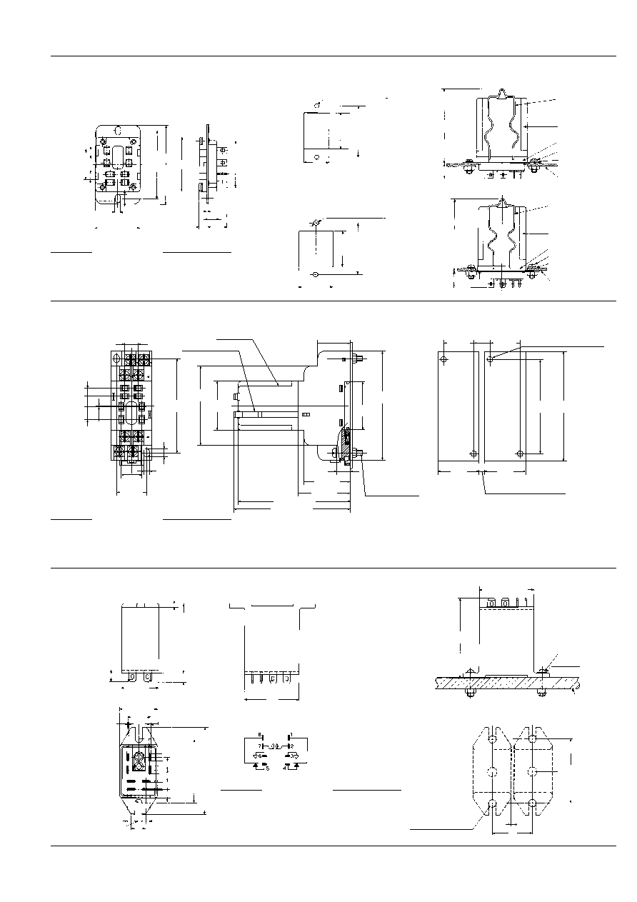
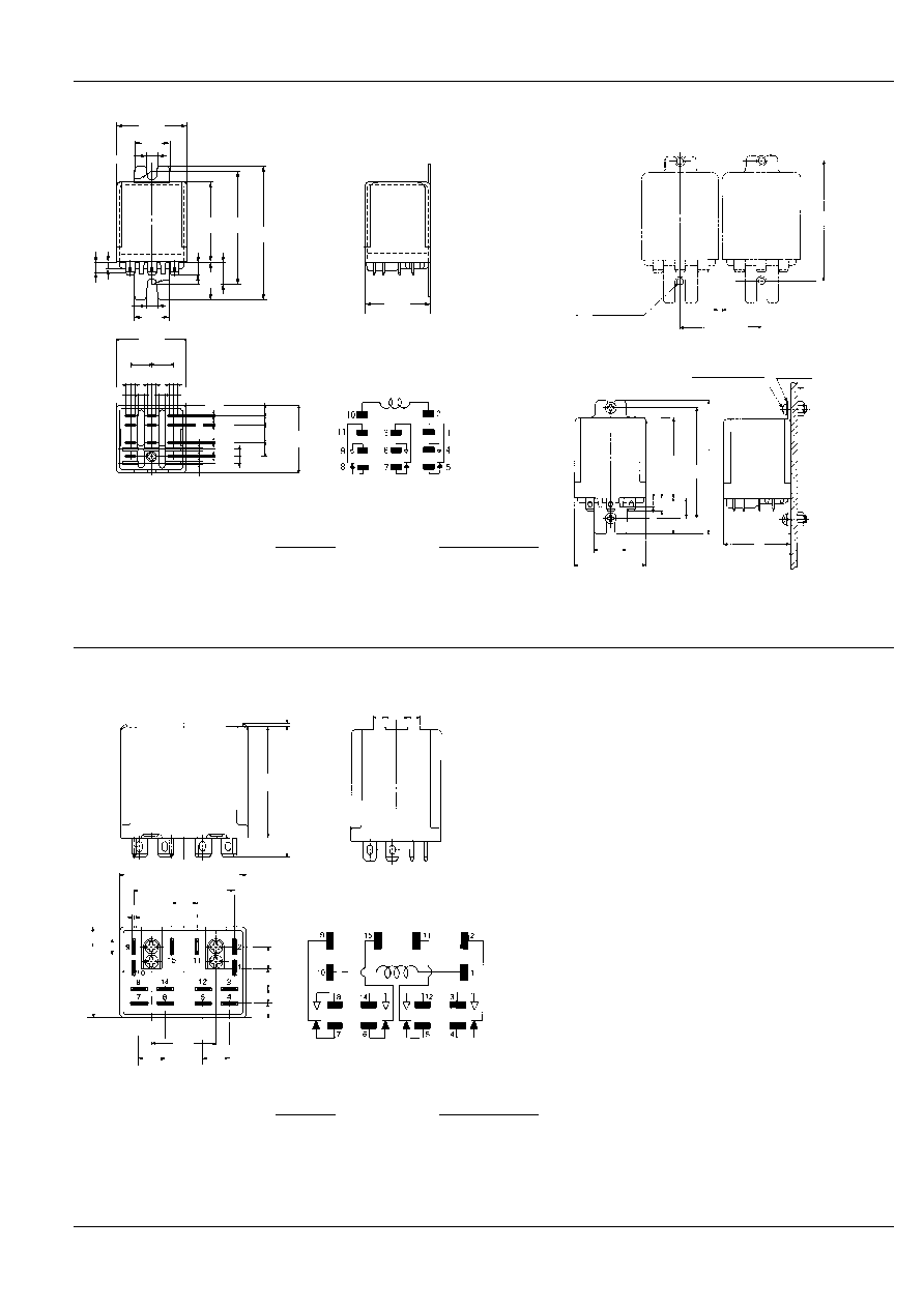
DIMENSIONS AND WIRING DIAGRAM
HP2 (2 Form C) Plug-in terminal types
0.5
.020
44
1.732
51
2.008
5
.197
5
.197
8
.315
25
.984
15
.591
0.8
.031
5.26
.207
10
.394
5.26
.207
36
1.417
9.5
.374
7.5
.295
5.8
.228
5.3
.209
Accepts
Faston 205
Circuit diagram
Dimension :
General tolerance
Max. 2mm
.079 inch
:
±
0.2
±
.008
2 to 9mm
.079 to .354 inch
:
±
0.5
±
.020
9 to 20mm
.354 to .787 inch
:
±
1.0
±
.039
Min. 20mm
.787 inch
:
±
1.5
±
.059
mm
inch
HP
417
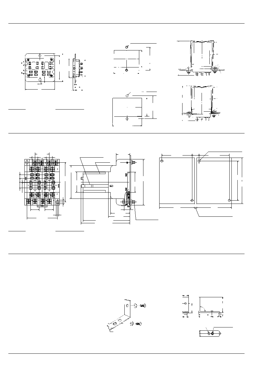
HP2-SRS (with hold-down clip)
Optimum space-saving panel cut-out.
Can be mounted from either the front or
the rear of the panel.
5
.197
5
.197
22
.866
4.1
.161
6.2
.244
1.0
.039
6
.236
30
1.181
56
2.205
48
±
0.2
1.890
±
.008
38
1.496
33
1.299
5.5
.217
13
.512
Front surface-mounting
Rear surface-mounting
48
±
0.5
1.890
±
.020
34
+1
≠0
1.339
+0.39
≠0
24
+0.1
≠0
.945
+.004
≠0
4.2
±
0.1 DIA. HOLE or
4 mm SCREW HOLE
.165
±
.004 DIA. HOLE
48
±
0.5
1.890
±
.020
39
1.535
31
1.220
4.2
±
0.1 DIA. HOLE or
4 mm SCREW HOLE
.165
±
.004 DIA. HOLE
57.9
±
3
2.280
±
.118
HOLD-DOWN CLIP
HP RELAY
HP SOCKET
4 mm SCREW
SPRING WASHER
PANEL
HOLD-DOWN CLIP
HP RELAY
HP SOCKET
4 mm SCREW
SPRING WASHER
PANEL
13
.512
56.9
±
3
2.240
±
.118
14
.551
mm
inch
HP2-SFD (with hold-down clip)
Front wiring in restricted space
23.8
±
0.6
.937
±
.024
HOLD DOWN CLIP
HP2 RELAY
Installation screw
block
(installation screw,
hexagonal nut,
spring washer)
5.8
±
0.2
.228
±
.008
7.5
±
0.2
.295
±
.008
9.5
±
0.2
.374
±
.008
4.1
±
0.3
.161
±
.012
6
±
0.3
.236
±
.012
35.4
±
0.5
1.394
±
.020
0.6
±
0.15
.024
±
.006
10
±
0.2
.394
±
.008
22
±
0.6
.866
±
.024
15
±
0.2
.591
±
.008
80
±
1
3.150
±
.039
10
±
0.6
.394
±
.024
37.9
±
0.6
1.492
±
.024
33.8
±
0.6
1.331
±
.024
Max. 85
3.346
Max. 89
3.504
58
±
1
2.283
±
.039
36
±
1
1.417
±
.039
69
±
1
2.717
±
.039
Mounting dimensions
Note: Hold down clip and installation screw block are
included in package.
Panel hole dimensions
for side-by-side installation
12
.472
22
±
0.2
.866
±
.008
22
±
0.2
.866
±
.008
30
1.181
30
1.181
4
.157
69
±
0.5
2.717
±
.020
80
3.150
2-M4
.157
SCREW HOLE or
4.2
±
0.1
.165
±
.004
DIA. HOLE
HP2-TM (2 Form C) Top mounting types
2.8
.110
46.8
1.843
24.7
.972
0.8
.031
0.8
.031
45.5
1.791
35.7
1.406
5.26
.207
5.26
.207
4.5
.177
10
.394
9.5
.374
5.5
.217
7.5
.295
5.8
.228
5.3
.209
2.25R
.089R
58
2.283
25
.984
15
.591
7
.276
Accepts
Faston 205
Circuit diagram
Mounting dimensions
52.3
2.059
35.7
1.406
4 mm SCREW or
8-32 NC-2 SCREW
SCREW WASHER
PANEL
45.5
1.791
2
.079
30
1.181
4.5
±
0.1 DIA. HOLE or
4 mm SCREW HOLE
.117
±
.004 DIA. HOLE
Dimension :
General tolerance
Max. 2mm
.079 inch
:
±
0.2
±
.008
2 to 9mm
.079 to .354 inch
:
±
0.5
±
.020
9 to 20mm
.354 to .787 inch
:
±
1.0
±
.039
Min. 20mm
.787 inch
:
±
1.5
±
.059
Dimension :
General tolerance
Max. 2mm
.079 inch
:
±
0.2
±
.008
2 to 9mm
.079 to .354 inch
:
±
0.5
±
.020
9 to 20mm
.354 to .787 inch
:
±
1.0
±
.039
Min. 20mm
.787 inch
:
±
1.5
±
.059
Dimension :
General tolerance
Max. 2mm
.079 inch
:
±
0.2
±
.008
2 to 9mm
.079 to .354 inch
:
±
0.5
±
.020
9 to 20mm
.354 to .787 inch
:
±
1.0
±
.039
Min. 20mm
.787 inch
:
±
1.5
±
.059
HP
418
HP3 (3 Form C) Plug-in terminal types
38
1.496
0.5
.020
44
1.732
3
.118
5
.197
7
.276
36
1.417
4.75
.187
11
.433
11
.433
38
1.496
0.5
.020
2
.079
2
.079
4
.157
36
1.417
5.75
.226
5.5
.217
8.5
.335
7.65
.301
4.1
.161
5
.197
8
.315
5
.197
Accepts
Faston 187
Circuit diagram
mm
inch
HP3-SRS (with hold-down clip)
Optimum space-saving panel cut-out.
Can be mounted from either the front or
the rear of the panel.
22.23
.875
56
2.205
0.6
.024
7.65
.301
2.75
.108
8.5
.335
38
1.496
22
.866
42.95
1.691
4.1
.161
3.5
.138
5
.197
5
.197
3.5
.138
6.2
.244
48
±
0.2
1.890
±
.008
Lot No.
45
1.772
14.5
.571
4.2
+
0.2
-
0
dia.
.165
+
.008
-
0
dia.
11
.433
11
.433
8
.315
1
.039
5.5
.217
30
1.181
5.5
.217
Front surface-mounting
Rear surface-mounting
48
±
0.5
1.890
±
.020
31
+1
≠0
1.220
+0.39
≠0
31
+1
≠0
1.220
+.039
≠0
4.2
±
0.1 DIA. HOLE or
4 mm SCREW HOLE
.165
±
.004 DIA. HOLE
48
±
0.5
1.890
±
.020
39
+1
≠0
1.535
+.039
≠0
46
+1
≠0
1.811
+.039
≠0
4.2
±
0.1 DIA. HOLE or
4 mm SCREW HOLE
.165
±
.004 DIA. HOLE
3.5
.138
30
1.181
40
±
0.3
1.575
±
.012
52
±
0.3
2.047
±
.012
HOLD DOWN CLIP
HP RELAY
HP3-SFD (with hold-down clip)
Front wiring in restricted space
Note: Hold down clip and installation screw block are included in package.
69
±
1
2.717
±
.039
80
±
1
3.150
±
.039
HOLD DOWN CLIP
HP3 RELAY
35.4
±
0.5
1.394
±
.020
58
±
1
2.283
±
.039
36
±
1
1.417
±
.039
6
±
0.3
.236
±
.012
37
±
0.6
1.457
±
.024
4.1
±
0.3
.161
±
.012
22
±
0.2
.866
±
.008
5.5
±
0.2
.217
±
.008
8.5
±
0.2
.335
±
.008
7.65
±
0.2
.301
±
.008
1.75
±
0.15
.069
±
.006
Max. 85
3.346
Max. 89
3.504
10
±
0.6
.394
±
.024
33.8
±
0.6
1.331
±
.024
37.9
±
0.6
1.492
±
.024
23.8
±
0.6
.937
±
.024
Installation screw
block
(installation screw,
hexagonal nut,
spring washer)
Mounting dimensions
12
.472
37
±
0.2
1.457
±
.008
37
±
0.2
1.457
±
.008
2-M4
.157
SCREW HOLE or
4.2
±
0.1
.165
±
.004
DIA. HOLE
Panel hole dimensions
for side-by-side installation
45
1.772
45
1.772
4
.157
69
±
0.5
2.717
±
.020
80
3.150
Dimension :
General tolerance
Max. 2mm
.079 inch
:
±
0.2
±
.008
2 to 9mm
.079 to .354 inch
:
±
0.5
±
.020
9 to 20mm
.354 to .787 inch
:
±
1.0
±
.039
Min. 20mm
.787 inch
:
±
1.5
±
.059
Dimension :
General tolerance
Max. 2mm
.079 inch
:
±
0.2
±
.008
2 to 9mm
.079 to .354 inch
:
±
0.5
±
.020
9 to 20mm
.354 to .787 inch
:
±
1.0
±
.039
Min. 20mm
.787 inch
:
±
1.5
±
.059
Dimension :
General tolerance
Max. 2mm
.079 inch
:
±
0.2
±
.008
2 to 9mm
.079 to .354 inch
:
±
0.5
±
.020
9 to 20mm
.354 to .787 inch
:
±
1.0
±
.039
Min. 20mm
.787 inch
:
±
1.5
±
.059
HP
419
HP3-M (3 Form C) Direct mounting types
2.1R
2.1R
38
1.496
16
.630
44
1.732
20.5
.807
16
.630
38
1.496
4.75
.187
4.75
.187
4.75
.187
36
1.417
2
.079
2
.079
0.5
.020
5.5
.217
5.75
.226
8.5
.335
7.65
.301
4.1
.161
0.5
.020
0.5
.020
0.5
.020
2.5
.098
2.5
.098
11
.433
11
.433
36
1.417
4.2
.165
7
.276
5
.197
3
.118
11
.433
60
2.362
73.5
2.894
4.2
.165
Accepts
Faston 187
Circuit diagram
Dimension :
General tolerance
Max. 2mm
.079 inch
:
±
0.2
±
.008
2 to 9mm
.079 to .354 inch
:
±
0.5
±
.020
9 to 20mm
.354 to .787 inch
:
±
1.0
±
.039
Min. 20mm
.787 inch
:
±
1.5
±
.059
Mounting dimension
60
2.362
MIN. 2
.079
MIN. 40
1.575
4.2
±
0.1 DIA. HOLE or
4 mm SCREW HOLE
.165
±
.004 DIA. HOLE
4 mm SCREW or
8-32 NC-2 SCREW
SPRING
WASHER
36
1.417
16
.630
44
1.732
60
2.362
73.5
2.894
11
.433
20.5
.807
7
.276
5
.197
38
1.496
mm
inch
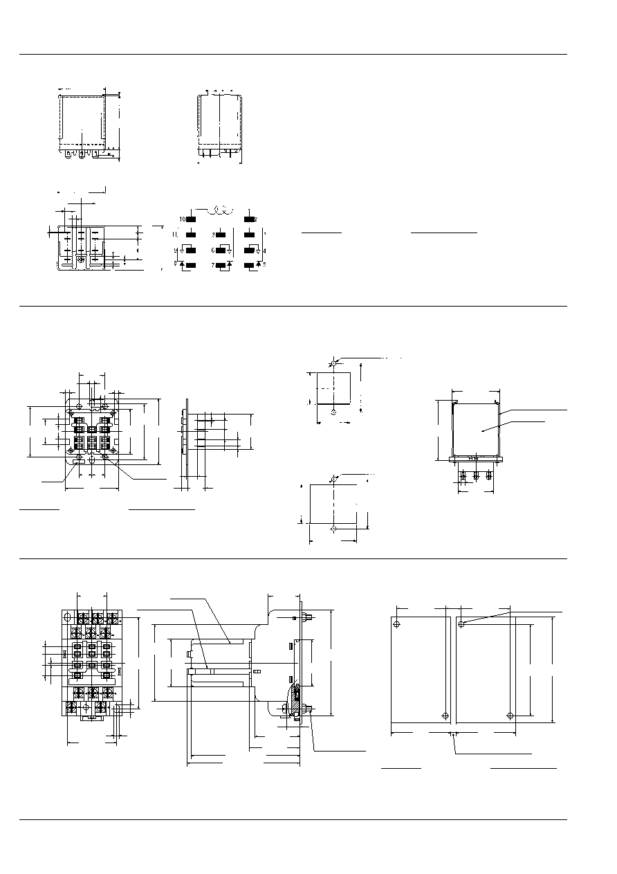
HP4 (4 Form C) Plug-in terminal types
0.5
.020
5
.197
8
.315
5
.197
44
1.732
51
2.008
50
1.969
40
1.575
10
.394
0.8
.031
5.26
.207
36
1.417
25
.984
10
.394
10
.394
9.5
.374
7.5
.295
5.8
.228
5.3
.209
Circuit diagram
Dimension :
General tolerance
Max. 2mm
.079 inch
:
±
0.2
±
.008
2 to 9mm
.079 to .354 inch
:
±
0.5
±
.020
9 to 20mm
.354 to .787 inch
:
±
1.0
±
.039
Min. 20mm
.787 inch
:
±
1.5
±
.059
Accepts
Faston 187
HP
420
HP4-SRS (with hold-down clip)
Optimum space-saving panel cut-out.
Can be mounted from either the front or
the rear of the panel.
5
.197
5
.197
56
2.205
22
.866
4.1
.161
6.2
.244
58
2.283
38
1.496
33
1.299
5.5
.217
13
.512
1.0
.039
6
.236
48
±
0.2
1.890
±
.008
Front surface-mounting
Rear surface-mounting
48
±
0.5
1.890
±
.020
4.2
±
0.1 DIA. HOLE or
4 mm SCREW HOLE
.165
±
.004 DIA. HOLE
34
+1
≠0
1.339
+.039
≠0
48
+1
≠0
+.039
≠0
48
±
0.5
1.890
±
.020
4.2
±
0.1 DIA. HOLE or
4 mm SCREW HOLE
.165
±
.004 DIA. HOLE
39
+1
≠0
1.535
+.039
≠0
58
+1
≠0
2.284
+.039
≠0
53
±
3
2.087
±
.118
13
.512
HOLD-DOWN CLIP
HP RELAY
HP SOCKET
SPRING WASHER
PANEL
4 mm SCREW
52
±
3
2.047
±
.118
14
.551
HOLD-DOWN CLIP
HP RELAY
HP SOCKET
SPRING WASHER
PANEL
4 mm SCREW
mm
inch
HP4-SFD (with hold-down clip)
Front wiring in restricted space.
Two HP2 relays can be mounted in one socket.
80
±
1
3.150
±
.039
35.4
±
0.5
1.394
±
.020
23.8
±
0.6
.937
±
.024
Installation screw
block
(installation screw,
hexagonal nut,
spring washer)
Max. 85
3.346
Max. 89
3.504
10
±
0.6
.394
±
.024
33.8
±
0.6
1.331
±
.024
37.9
±
0.6
1.492
±
.024
HOLD DOWN CLIP
HP4 RELAY
58
±
1
2.283
±
.039
36
±
1
1.417
±
.039
69
±
1
2.717
±
.039
6
±
0.3
.236
±
.012
53
±
0.6
2.087
±
.024
15
±
0.2
.591
±
.008
15
±
0.2
.591
±
.008
4.1
±
0.3
.161
±
.012
25
±
0.1
.984
±
.004
5.8
±
0.2
.228
±
.008
10
±
0.2
.394
±
.008
10
±
0.2
.394
±
.008
7.5
±
0.2
.295
±
.008
9.5
±
0.2
.374
±
.008
0.6
±
0.15
.024
±
.006
Mounting dimensions
12
.472
53
±
0.2
2.087
±
.008
53
±
0.2
2.087
±
.008
2-M4
.157
SCREW HOLE or
4.2
±
0.1
.165
±
.004
DIA. HOLE
Panel hole dimensions
for side-by-side installation
61
2.402
61
2.402
4
.157
69
±
0.5
2.717
±
.020
80
3.150
Note: Hold down clip and installation screw block are
included in package.
ACCESSORIES for HP2 and HP4 types
HP Bracket (with 2 screws, 2 washers)
The HP Bracket is used for mounting HP2
relays and HP4 relays directly to the pan-
el. It facilitates soldering or quick connec-
tions with Faston 205 tab 0.8 mm
.031
inch
.
Notes:
1. This bracket is unavailable for UL, CSA
and VDE applications.
2. When using the special bracket, it is
recommended to use the screws and
washers called out in the chart in the next
page in order to eliminate any possible
damage to the relay coil.
Mounting methods
(a) Remove the M3
◊
7 screw (red col-
ored) fixed to the relay, and place the
bracket on the relay with the attaching M3
◊
7 screw (blue colored) and the spring
washer.
(b) Use the additional M3
◊
7 screw and
washer for attaching the bracket to the
panel.
For the HP4 type relay
two brackets are used
Keying tab.
8
.315
14
.551
4
.158
23
.906
20
.787
8.5
.335
1
.039
14
.551
90
∞±
3
∞
2
.079
3.5 DIA. HOLE
.138 DIA. HOLE
3 DIA. HOLE
.118 DIA. HOLE
Dimension :
General tolerance
Max. 2mm
.079 inch
:
±
0.2
±
.008
2 to 9mm
.079 to .354 inch
:
±
0.5
±
.020
9 to 20mm
.354 to .787 inch
:
±
1.0
±
.039
Min. 20mm
.787 inch
:
±
1.5
±
.059
Dimension :
General tolerance
Max. 2mm
.079 inch
:
±
0.2
±
.008
2 to 9mm
.079 to .354 inch
:
±
0.5
±
.020
9 to 20mm
.354 to .787 inch
:
±
1.0
±
.039
Min. 20mm
.787 inch
:
±
1.5
±
.059

HP
421
Dimensions and mounting method
25
.984
50
1.969
8.5
.335
8.5
.335
MIN.
26
1.024
MIN.
26
1.024
20
.787
25
.984
25
.984
42
1.654
27
1.063
51
2.008
KEYING TAB
3 mm SCREW
3 mm SCREW
PANEL
BRACKET
BRACKET
42
1.654
28.5
1.122
44
1.732
51
2.008
KEYING
TAB
3 mm SCREW
3 mm SCREW
PANEL
20
.787
7
.276
7
.276
51
2.008
51
2.008
4.5 DIA. HOLE
.177 DIA. HOLE
4.5 DIA. HOLE
.177 DIA. HOLE
3.2 DIA. HOLE
.126 DIA. HOLE
3.2 DIA. HOLE
.126 DIA. HOLE
50
1.969
MIN.
26
1.024
25
.984
25
.984
4.5 DIA. HOLE
.177 DIA. HOLE
25
.984
44
1.732
MIN.
26
1.024
13
.512
14.5
.571
44
1.732
13
.512
14.5
.571
4.5 DIA. HOLE
.177 DIA. HOLE
HP2
HP4
1. Rear-surface mounting
2. Front-surface mounting
mm
inch
HP Inserting Plate for HP2 and HP4 types
1. HP inserting plate is used for mounting
HP2 and HP4 relays on a printed board to
adjust the length of the terminals.
2. If adjustment by soldering is not suit-
able, bore 1/8" diameter hole on the print-
ed circuit board and mount the relay with
a M3
◊
10 screw. The chart to the right
suggests the proper screws for different
printed circuit boards.
3. Two plates are used for the HP4 type
relay.
Thickness of P/C board
Suitable screw
1.0 mm
.039 inch
M3
◊
10
1.2 mm
.047 inch
M3
◊
10
PC board pattern
15
.591
3
.118
3
.118
36
1.417
16
.630
7.3
.287
4.5
.177
16.5
.650
25
.984
2
.079
8
.315
4 DIA. HOLE
.157 DIA. HOLE
Please refer to the above second instruction.
10
.394
1.0
.039
1.0
.039
10
.394
10
.394
25
.984
7.5
.295
7.5
.295
9.5
.374
9.5
.374
15
.591
15
.591
15
.591
8.9
.350
8.9
.350
5.8
.228
5.8
.228
5.8
.228
5.8
.228
3.2 DIA. HOLE
.126 DIA. HOLE
3.2 DIA. HOLE
.126 DIA. HOLE
HP2
HP4
Tolerance:
±
0.1
±
.004
46
1.811
5
.197
HP INSERTION
PLATE
PC BOARD
For Cautions for Use, see Relay Technical Information (Page 48 to 76).
Thickness of a special bracket
1.0 mm (
.039 inch
)
1.6 mm (
.063 inch
)
2.0 mm (
.079 inch
)
A suitable screw
M3
◊
7-M3
◊
8
M3
◊
8
M3
◊
8-M3
◊
10
A suitable washer
for M3
for M3
for M3
Screw M 3
◊
7
Millimeter
3mm
.118inch
diameter
7mm
.276inch
length
9/1/2000
All Rights Reserved, © Copyright Matsushita Electric Works, Ltd.
Go To Online Catalog