 | –≠–ª–µ–∫—Ç—Ä–æ–Ω–Ω—ã–π –∫–æ–º–ø–æ–Ω–µ–Ω—Ç: JQ1A-9V | –°–∫–∞—á–∞—Ç—å:  PDF PDF  ZIP ZIP |

71
JQ RELAYS
VDE
HIGH ELECTRICAL &
MECHANICAL NOISE
IMMUNITY RELAY
mm
inch
20
.787
10
.394
15.6
.614
FEATURES
∑ High electrical noise immunity
∑ High switching capacity in a compact package
∑ High sensitivity: 200 mW (1a), 400 mW (1c)
∑ High surge voltage: 8,000 V between contacts and coil
∑ UL, CSA, VDE, TÐV, SEMKO approved
∑ Class B coil insulation type available
SPECIFICATIONS
Contact
Expected electrical life (min. operations)
Coil (at 20
∞
C
68
∞
F
)
Characteristics
Remarks
*
Specifications will vary with foreign standards certification ratings.
*
1
Measurement at same location as "Initial breakdown voltage" section
*
2
Detection current: 10 mA
*
3
Wave is standard shock voltage of
±
1.2
◊
50
µ
s according to JEC-212-1981
*
4
Excluding contact bounce time
*
5
Measured conditions
*
6
Half-wave pulse of sine wave: 11ms; detection time: 10
µ
s
*
7
Half-wave pulse of sine wave: 6ms
*
8
Detection time: 10
µ
s
*
9
Refer to 5. Conditions for operation, transport and storage mentioned in
AMBIENT ENVIRONMENT (Page 24).
*
10
When using relays in a high ambient temperature, consider the pick-up voltage
rise due to the high temperature (a rise of approx. 0.4% V for each 1∞C
33.8∞F
with 20∞C
68∞F
as a reference) and use a coil impressed voltage that is within
the maximum allowable voltage range.
Standard type
High capacity type
Arrangement
1 Form A, 1 Form C
Initial contact resistance, max.
(By voltage drop 6 V DC 1 A)
100 m
Contact material
Silver alloy
Rating
(resistive)
Nominal
switching
capacity
1a
5 A 125 V AC
2 A 250 V AC
5 A 30 V DC
10 A 125 V AC
5 A 250 V AC
5 A 30 V DC
1c
N.O.
5 A 125 V AC
2 A 250 V AC
3 A 30 V AC
10 A 125 V AC
5 A 250 V AC
5 A 30 V DC
N.C.
2 A 125 V AC
1 A 250 V AC
1 A 30 V DC
3 A 125 V AC
2 A 250 V AC
1 A 30 V DC
Max.
switching
power
1a
625 VA, 150 W
1,250 VA, 150 W
1c
N.O.
625 VA, 90 W
1,250 V AC, 150 W
N.C.
250 VA, 30 W
500 V AC, 30 W
Max. switching voltage
250 V AC, 110 V DC (0.3A)
Max. switching current
N.O.: 5 A N.C.: 2 A
N.O.: 10 A N.C.: 3 A
Expected mechanical life
(at 180 cpm)(min. operations)
10
7
Type
Switching capacity
No. of operations
Standard type
1a
5 A 125 V AC
3 A 125 V AC
2 A 250 V AC
5 A 30 V DC
5
◊
10
4
2
◊
10
5
2
◊
10
5
10
5
1c
N.O.
5 A 125 V AC
2 A 250 V AC
3 A 30 V DC
5
◊
10
4
2
◊
10
5
10
5
N.C.
2 A 125 V AC
1 A 250 V AC
1 A 30 V DC
2
◊
10
5
2
◊
10
5
10
5
High capacity
type
1a
10 A 125 V AC
5 A 250 V AC
5 A 30 V DC
5
◊
10
4
5
◊
10
4
10
5
1c
N.O.
10 A 125 V AC
5 A 250 V AC
5 A 30 V DC
5
◊
10
4
5
◊
10
4
10
5
N.C.
3 A 125 V AC
2 A 250 V AC
1 A 30 V DC
2
◊
10
5
2
◊
10
5
10
5
Nominal operating power
1a: 200 mW
1c: 400 mW
Max. operating speed
20 cpm
Initial insulation resistance*
1
Min. 1,000 M
at 500 V DC
Initial
breakdown
voltage*
2
Between open contacts
1a: 1,000 Vrms for 1 min.
1c: 750 Vrms for 1 min.
Between contacts and coil
4,000 Vrms for 1 min.
Surge voltage between
contact and coil*
3
8,000 V
Operate time*
4
(at nominal voltage)
Approx. 5 ms
Release time*
4
(at nominal voltage)(without diode)
Approx. 2 ms
Temperature rise*
5
Max. 45
∞
C
Shock
resistance
Functional*
6
Min. 294 m/s
2
{30 G}
Destructive*
7
Min. 980 m/s
2
{100 G}
Vibration
resistance
Functional*
8
98 m/s
2
{10 G}, 10 to 55 Hz
at double amplitude of 1.6 mm
Destructive
117.6 m/s
2
{12 G}, 10 to 55 Hz
at double amplitude of 2.0 mm
Conditions for operation,
transport and storage*
9
(Not freezing and condens-
ing at low temperature)
Ambient
temp.*
10
≠40
∞
C to +85
∞
C
≠40
∞
F to +185
∞
F
Humidity
5 to 85% R.H.
Unit weight
Approx. 7 g .
25 oz
Standard type
Resistive, nominal voltage applied to the coil.
Contact carrying current: 5 A, at 70
∞
C
158∞F
High capacity type
Resistive, nominal voltage applied to the coil.
Contact carrying current: 10 A, at 70
∞
C
158∞F
JQ
72
TYPES AND COIL DATA at 20
∞
C
68
∞
F
Part No.
Nominal
voltage, V DC
Pick-up
voltage, V DC
(min.)
Drop-out
voltage, V DC
(min.)
Nominal
operating
current, mA
Nominal
operating
power, mW
Coil resistance,
(
±
10%)
Max. allowable
voltage, V DC
1 F
o
r
m
A
Standard type
JQ1a-5V
5
3.75
0.25
40
200
125
180% of
nominal voltage
(at 20
∞
C
68∞F
)
JQ1a-6V
6
4.5
0.3
33.3
180
JQ1a-9V
9
6.75
0.45
22.2
405
JQ1a-12V
12
9
0.6
16.7
720
JQ1a-18V
18
13.5
0.9
11.1
1,620
JQ1a-24V
24
18
1.2
8.3
2,880
High capacity type
JQ1aP-5V
5
4
0.25
40
200
125
130% of
nominal voltage
(at 85
∞
C
185∞F
)
JQ1aP-6V
6
4.8
0.3
33.3
180
JQ1aP-9V
9
7.2
0.45
22.2
405
JQ1aP-12V
12
9.6
0.6
16.7
720
JQ1aP-18V
18
14.4
0.9
11.1
1,620
JQ1aP-24V
24
19.2
1.2
8.3
2,880
1 F
o
r
m
C
Standard type
JQ1-5V
5
3.75
0.25
80
400
62.5
150% of
nominal voltage
(at 20
∞
C
68∞F
)
JQ1-6V
6
4.5
0.3
66.7
90
JQ1-9V
9
6.75
0.45
44.4
202.5
JQ1-12V
12
9
0.6
33.3
360
JQ1-18V
18
13.5
0.9
22.2
810
JQ1-24V
24
18
1.2
16.7
1,440
JQ1-48V
48
36
2.4
8.3
5,760
High capacity type
JQ1P-5V
5
4
0.25
80
400
62.5
110% of
nominal voltage
(at 85
∞
C
185∞F
)
JQ1P-6V
6
4.8
0.3
66.7
90
JQ1P-9V
9
7.2
0.45
44.4
202.5
JQ1P-12V
12
9.6
0.6
33.3
360
JQ1P-18V
18
14.4
0.9
22.2
810
JQ1P-24V
24
19.2
1.2
16.7
1,440
JQ1P-48V
48
38.4
2.4
8.3
5,760
TYPICAL APPLICATIONS
∑ Air conditioners
∑ Refrigerators
∑ Microwave ovens
∑ Heaters
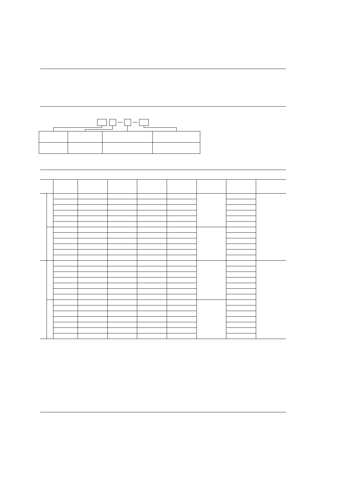
ORDERING INFORMATION
Contact
arrangement
1a: 1 Form A
1: 1 Form C
Nil: Standard
P: High capacity
5, 6, 9, 12, 18, 24, 48* V
Contact capacity
Nil: Class E coil insulation
B: Class B coil insulation
Coil insulation class
Coil voltage (DC)
UL/CSA, VDE, SEMKO approved type is standard.
* Available only for 1 Form C type
1a
P
B
Ex. JQ
12
V
JQ
73
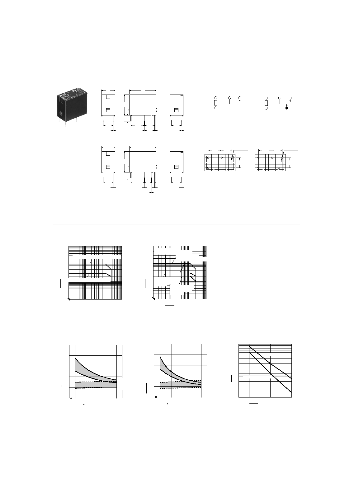
REFERENCE DATA
Max. switching capacity (1 Form A type)
Max. switching capacity (1 Form C type)
AC resistive load (High capacity type)
AC resistive load (Standard type)
1
10
100 277
1,000
10
100
5
Contact voltage, V
Contact current, A
1
10
100 277
1,000
10
100
2
3
5
Contact voltage, V
Contact current, A
AC resistive load
(High capacity type) N.O. side
AC resistive load
(High capacity type)
N.C. side
AC resistive load
(Standard type) N.O. side
AC resistive load
(Standard type)
N.C. side
Standard type
1-(1). Operate & release time
(1 Form A type)
Tested sample: JQ1a-12V, 25 pcs.
1-(2). Operate & release time
(1 Form C type)
Tested sample: JQ1-24V, 25 pcs.
2. Life curve
Ambient temperature: room temperature
80
100
120
150
2
0
4
6
8
Coil applied voltage, %V
Operate & release time, ms
Operate time
Release time
Max.
Max.
Min.
Min.
80
100
120
150
2
0
4
6
8
Coil applied voltage, %V
Operate & release time, ms
Operate time
Release time
Min.
Min.
Max.
Max.
100
10
1
1
0
2
3
4
5
Contact current, A
125V AC resistive load
250V AC resistive load
Life,
◊
10
4
DIMENSIONS
mm
inch
1 Form A
1 Form C
Dimension :
General tolerance
Max. 1mm
.039 inch
±
0.2
±
.008
1 to 5mm
.039 to .118 inch
±
0.3
±
.012
Min. 5mm
.118 inch
±
0.4
±
.016
20
.787
15.6
.614
4.2
.165
0.4
.016
10.16
.400
7.62
.300
7.62
.300
7.62
.300
10
.394
0.3
.012
0.3
.012
0.5 dia.
.020 dia.
0.8
.031
4.2
.165
0.4
.016
20
.787
15.6
.614
10.16
.400
5.08
.200
2.54
.100
7.62
.300
7.62
.300
0.3
.012
0.3
.012
0.3
.012
0.5 dia.
.020 dia.
0.8
.031
10
.394
Schematic (Bottom view)
1 Form A
1 Form C
Coil
COM
N.O.
Coil
COM
N.O.
N.C.
PC board pattern (Copper-side view)
1 Form A
1FormC
Tolerance:
±
0.1
±
.004
4-1.3 dia.
4-.051 dia.
7.62
.300
7.62
.300
10.16
.400
5-1.3 dia.
5-.051 dia.
7.62
.300
7.62
.300
10.16
.400

JQ
74
3-(1). Coil temperature rise
(1 Form A type)
Contact carrying current: 3 A, 5 A
Measured portion: Inside the coil
3-(2). Coil temperature rise
(1 Form C type)
Contact carrying current: 3 A, 5 A
Measured portion: Inside the coil
100 110 120 130 140
160
190
180
170
150
10
20
30
40
50
0
Coil applied voltage, %V
Temperature rise,
∞
C
3 A at 85
∞
C
5 A at 85
∞
C
3 A at 70
∞
C
5 A at 70
∞
C
100
110
120
130
140
160
150
10
20
30
40
50
60
70
0
Coil applied voltage, %V
Temperature rise,
∞
C
3 A at 70
∞
C
5 A at 70
∞
C
5 A at 85
∞
C
3 A at 85
∞
C
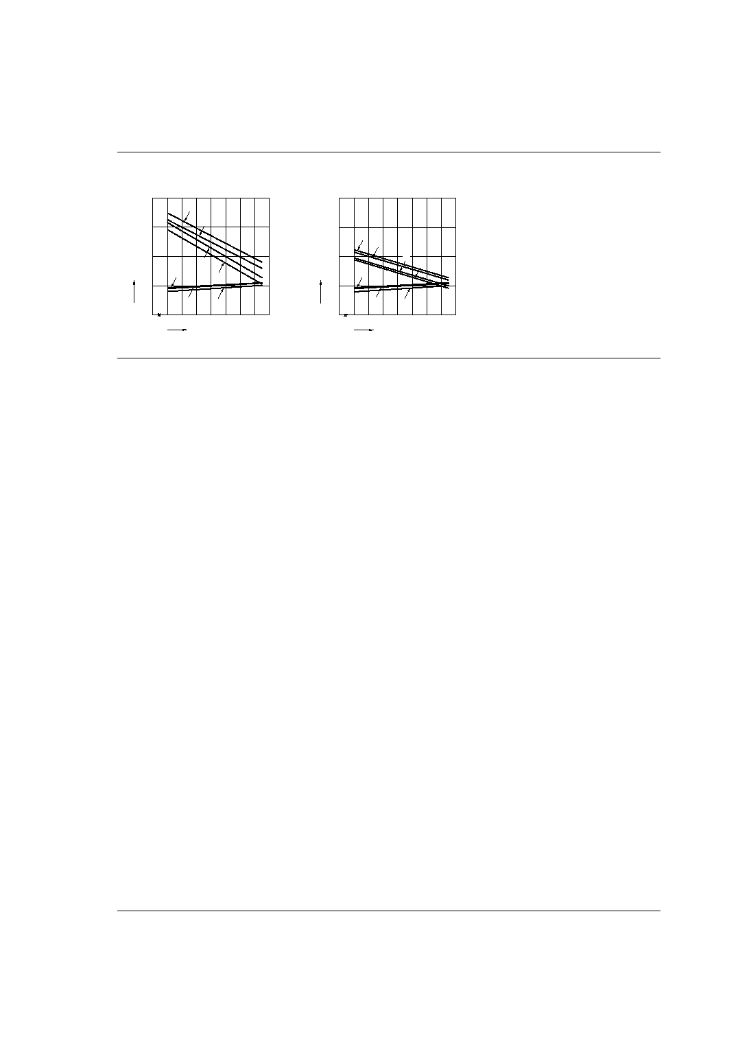
4-(1). Ambient temperature characteristics
(1 Form A type)
Tested sample: JQ1a-24V
Contact carrying current: 3 A, 5 A
4-(2). Ambient temperature characteristics
(1 Form C type)
Tested sample: JQ1-24V
Contact carrying current: 3 A, 5 A
1
Allowable ambient temperature against
% coil voltage (max. inside the coil temperature
set as 130
∞
C
266
∞
F
) (Carrying current: 3 A)
2
Allowable ambient temperature against
% coil voltage (max. inside the coil temperature
set as 130
∞
C
266
∞
F
) (Carrying current: 5 A)
3
Allowable ambient temperature against
% coil voltage (max. inside the coil temperature
set as 115
∞
C
239
∞
F
) (Carrying current: 3 A)
4
Allowable ambient temperature against
% coil voltage (max. inside the coil temperature
set as 115
∞
C
239
∞
F
) (Carrying current: 5 A)
5
Pick-up voltage with a hot-start condition
of 100%V on the coil (Carrying current: 5 A)
6
Pick-up voltage with a hot-start condition
of 100%V on the coil (Carrying current: 3 A)
7
Pick-up voltage
20
30
40
50
60
70
80
90
0
100
200
300
400
Ambient temperature,
∞
C
Coil applied voltage, %V
1
5
6
4
7
3
2
20
30
40
50
60
70
80
90
0
100
200
300
400
Ambient temperature,
∞
C
Coil applied voltage, %V
1
3
4
5
7
6
2
High capacity type
1-(1). Operate & release time
(1 Form A type)
Tested sample: JQ1aP-12V, 25 pcs.
1-(2). Operate & release time
(1 Form C type)
Tested sample: JQ1P-12V, 25 pcs.
2. Life curve
Ambient temperature: room temperature
80
100
120
150
2
0
4
6
8
Coil applied voltage, %V
Operate & release time, ms
Operate time
Release time
Min.
Min.
Max.
Max.
80
100
120
150
2
0
4
6
8
Coil applied voltage, %V
Operate & release time, ms
Operate time
Release time
Min.
Min.
Max.
Max.
100
10
1
2
0
4
6
8
10
Contact current, A
125V AC resistive load
250V AC resistive load
Life,
◊
10
4
3-(1). Coil temperature rise
(1 Form A type)
Contact carrying current: 5 A, 10 A
Measured portion: Inside the coil
3-(2). Coil temperature rise
(1 Form C type)
Contact carrying current: 5 A, 10 A
Measured portion: Inside the coil
100
120
140
160
180
10
20
30
40
50
60
70
0
Coil applied voltage, %V
Temperature rise,
∞
C
10 A at 70
∞
C
10 A at 85
∞
C
5 A at 70
∞
C
5 A at 85
∞
C
Coil applied voltage, %V
Temperature rise,
∞
C
100
110
120
130
140
150
160
10
20
30
40
50
60
70
0
10 A at 70
∞
C
10 A at 85
∞
C
5 A at 70
∞
C
5 A at 85
∞
C
JQ
75
4-(1). Ambient temperature characteristics
(1 Form A type)
Tested sample: JQ1aP-24V
Contact carrying current: 5 A, 10 A
4-(2). Ambient temperature characteristics
(1 Form C type)
Tested sample: JQ1P-24V
Contact carrying current: 5 A, 10 A
1
Allowable ambient temperature against
% coil voltage (max. inside the coil temperature
set as 130
∞
C
266
∞
F
) (Carrying current: 5 A)
2
Allowable ambient temperature against
% coil voltage (max. inside the coil temperature
set as 130
∞
C
266
∞
F
) (Carrying current: 10 A)
3
Allowable ambient temperature against
% coil voltage (max. inside the coil temperature
set as 115
∞
C
239
∞
F
) (Carrying current: 5 A)
4
Allowable ambient temperature against
% coil voltage (max. inside the coil temperature
set as 115
∞
C
239
∞
F
) (Carrying current: 10 A)
5
Pick-up voltage with a hot-start condition
of 100%V on the coil (Carrying current: 10 A)
6
Pick-up voltage with a hot-start condition
of 100%V on the coil (Carrying current: 5 A)
7
Pick-up voltage
20
30
40
50
60
70
80
90
0
100
200
300
400
Ambient temperature,
∞
C
Coil applied voltage, %V
1
5
4
7
6
3
2
20
30
40
50
60
70
80
90
0
100
200
300
400
Ambient temperature,
∞
C
Coil applied voltage, %V
1
5
7
6
2
3
4
For Cautions for Use, see Relay Technical Information (Page 11 to 39).
12/27/2002
All Rights Reserved, © Copyright Matsushita Electric Works, Ltd.
Go To Online Catalog