98
JR-RELAYS
SLIM TYPE POWER RELAYS
High contact
capacity type
mm
inch
28.5
1.122
12.8
.504
28.6
1.126
TMP type
TM type
FEATURES
∑ AC coil types and high capacity (16 A) types
∑ Wide insulation distance: 8 mm
.315 inch
between coil and
contact
∑ High dielectric withstanding for transient protection: JR can
withstand 10,000 V surge in
µ
s between coil and contact.
∑ High inrush current capability: 1 Form A: 111 A inrush (TV-5),
∑ Slim package for tandem mounting: Header area is 28.6 mm
◊
12.8 mm
1.126
◊
.504 inch
∑ Molded materials: all 94 V-0
∑ "TM" and "TMP" types available
∑ TÐV also approved
SPECIFICATIONS
Contact
Coil
Characteristics
AC coil type
High capacity
type
Arrangement
1 Form A
Initial contact resistance
max.
(By voltage drop 6 V DC 1 A)
30 m
Contact material
Silver alloy
Rating
(resistive)
Nominal switching capacity
10 A 250 V AC
10 A 30 V DC
16 A 250 V AC
16 A 30 V DC
Maximum switching power
2,500 VA, 300 W 4,000 VA, 480 W
Maximum switching voltage
250 V AC, 30 V DC
250 V AC, 30 V DC
Maximum switching current
10 A
16 A
Expected
life (min.
operations)
Mechanical (180 cpm)
5
◊
10
6
Electrical
(resistive)
(20 cpm)
16 A 250 V AC
--
10
5
10 A 250 V AC
10
5
--
Nominal operating power
1.1 VA/0.9 VA
(at 50Hz/60Hz)
530mW
AC coil type
High capacity type
Maximum operating speed
20 cpm
Initial insulation resistance
Min. 1,000 M
at 500 V DC
Initial
breakdown
voltage*
1
Between open contacts
1,000 Vrms for 1 min.
Between contacts and coil
5,000 Vrms for 1 min.
Initial surge voltage between
coil and contact*
2
Min. 10,000 V
Operate time
(at nominal voltage)(at 20
∞
C)
Approx. 10 ms
Release time (without diode)
(at nominal voltage)(at 20
∞
C)
Approx. 6 ms
Approx. 2 ms
Temperature rise*
3
(at nominal voltage)
Max. 60
∞
C
(10 A, at 20∞C)
Max. 45
∞
C
(16 A, at 20∞C)
Shock
resistance
Functional*
4
Min. 98 m/s
2
{10 G}
Destructive*
5
Min. 980 m/s
2
{100 G}
Vibration
resistance
Functional*
6
88.2 m/s
2
{9 G}, 10 to 55 Hz
at double amplitude of 1.5 mm
Destructive
117.6 m/s
2
{12 G}, 10 to 55 Hz
at double amplitude of 2.0 mm
Conditions for operation,
transport and storage*
7
(Not freezing and condens-
ing at low temperature)
Ambient
temp.
≠50
∞
C to +55
∞
C
≠58
∞
F to +131
∞
F
≠50
∞
C to +70
∞
C
≠58
∞
F to +158
∞
F
Humidity
5 to 85% R.H.
Unit weight
Approx. 20 g
.71 oz
Remarks
* Specifications will vary with foreign standards certification ratings.
*
1
Detection current: 10mA
*
2
Wave is standard shock voltage of
±
1.2
◊
50
µ
s according to JEC-212-1981
*
3
With nominal coil voltage and at maximum switching current
*
4
Half-wave pulse of sine wave: 11ms; detection time: 10
µ
s
*
5
Half-wave pulse of sine wave: 6ms
*
6
Detection time: 10
µ
s
*
7
Refer to 5. Conditions for operation, transport and storage mentioned in
AMBIENT ENVIRONMENT (Page 24).
TYPICAL APPLICATIONS
∑ Microwave ovens
∑ Refrigerators
∑ Copiers
∑ Facsimiles
∑ Air conditioners
∑ Stereo equipment
∑ TV sets
∑ Vending machines
∑ Temperature controllers
ORDERING INFORMATION
1a
TM
DC12V
Ex. JR
Contact arrangement
Mounting method
Coil voltage
1aF: High contact capacity
(1 Form A)
1a: 1 Form A
Nil: PCB terminal
TM: Top mounting
TMP: Solder and PC teminal
DC 5, 6, 12, 24, 48 V
Notes: 1. For UL/CSA recognized types, add suffix UL/CSA.
Notes:
2. Standard packing: Carton: 100 pcs. Case: 500 pcs.
Notes:
3. 18 V DC type are also available. Please consult us for details.
TM: Top mounting
AC 115 V
JR
99
TYPES
High contact capacity types
1. PC board teminals (Double terminal layout)
2. "TMP" type
3. "TM" type
AC coil type
(Notes) 1. For UL/CSA recognized types, add suffix UL/CSA.
2. Standard packing Carton: 100 pcs., Case 500 pcs.
UL CSA TV rating types available
Contact arrangement
Coil voltage
Part No.
1a
5 V DC
JR1aF-DC5V
6 V DC
JR1aF-DC6V
12 V DC
JR1aF-DC12V
24 V DC
JR1aF-DC24V
48 V DC
JR1aF-DC48V
Contact arrangement
Coil voltage
Part No.
1a
5 V DC
JR1aF-TMP-DC5V
6 V DC
JR1aF-TMP-DC6V
12 V DC
JR1aF-TMP-DC12V
24 V DC
JR1aF-TMP-DC24V
48 V DC
JR1aF-TMP-DC48V
Contact arrangement
Coil voltage
Part No.
1a
5 V DC
JR1aF-TM-DC5V
6 V DC
JR1aF-TM-DC6V
12 V DC
JR1aF-TM-DC12V
24 V DC
JR1aF-TM-DC24V
48 V DC
JR1aF-TM-DC48V
1a
115 V AC
JR1a-TM-AC115V
Type
UL
CSA
JR1a AC coil type
TV-5
TV-5
JR1aF high capacity type
TV-5
TV-5
COIL DATA (at 20
∞
C
68
∞
F
)
Note: Coil resistance varies
±
10% for less than 1,000
coil and
±
15% for more than 1,000
.
For each
±
1
∞
C change in ambient temperature, coil resistance varies
±
0.4%.
*AC 100 V coil is available only for JR1a-TM type.
Contact
arrangement
Nominal voltage
Pick-up voltage,
(max.)
(Initial)
Drop-out
voltage,
(min.) (Initial)
Coil
resistance,
(
±
10%)
Nominal operating
current,
mA (
±
10%)
Nominal
operating power,
mW
Maximum
allowable
voltage,
(at 70
∞
C
158∞F
)
1 Form A
5 V DC
4.0 V DC
0.5 V DC
47
106
530
5.5 V DC
6 V DC
4.8 V DC
0.6 V DC
68
88
530
6.6 V DC
12 V DC
9.6 V DC
1.2 V DC
270
44
530
13.2 V DC
24 V DC
19.2 V DC
2.4 V DC
1,100
22
530
26.4 V DC
48 V DC
38.4 V DC
4.8 V DC
4.350
11
530
52.8 V DC
*115 V AC
92 V AC
34.5 V AC
--
7.8/9.1
(60 Hz)/(50 Hz)
0.9/1.1 VA
(60 Hz)/(50 Hz)
126.5V AC
(at 20
∞
C
68∞F
)
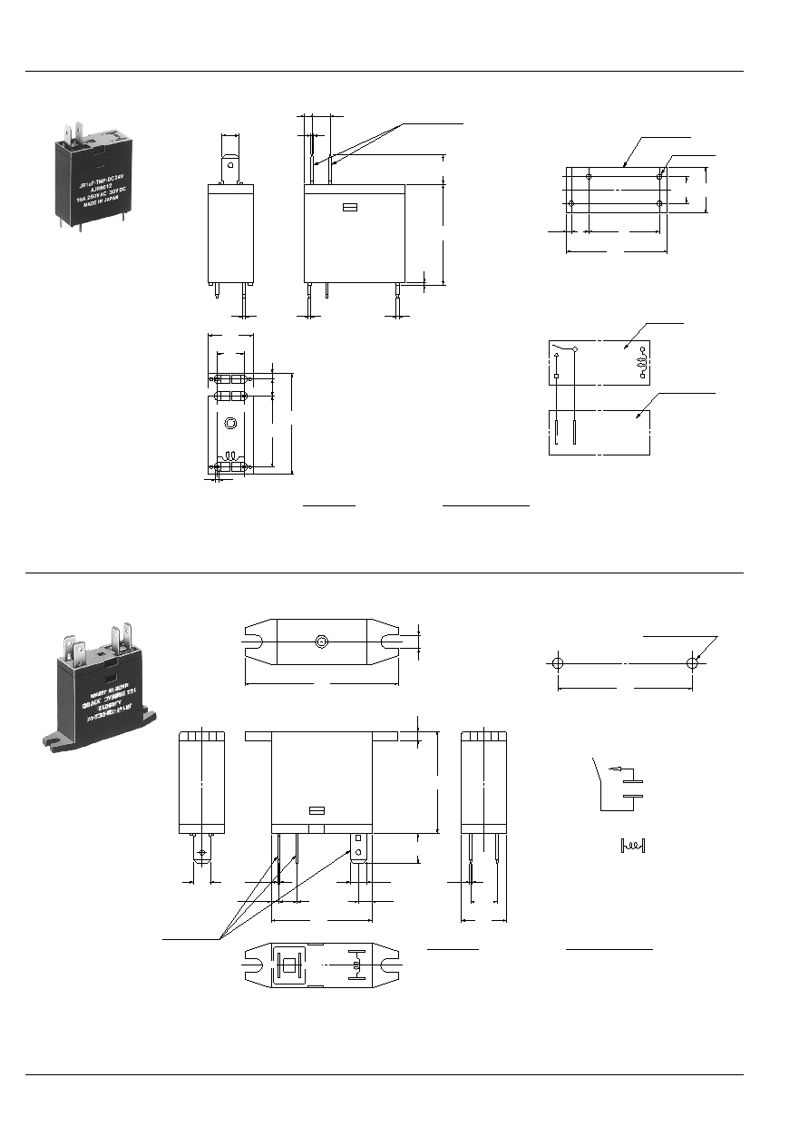
DIMENSIONS
mm
inch
∑ JR1aF (DC)
0.8
.031
28.5
1.122
0.8
.031
0.5
.020
0.5
.020
12.8
.504
28.6
1.126
20
.787
0.4
.016
1.45
.057
7.5
.295
5
.197
4
6
6
8
COM COM
N.O.
N.O.
1
4
Dimension :
General tolerance
Max. 1mm
.039 inch
±
0.1
±
.004
1 to 3mm
.039 to .118 inch
±
0.2
±
.008
Min. 3mm
.118 inch
±
0.3
±
.012
PC board pattern (Copper-side view)
Tolerance:
±
0.1
±
.004
Schematic (BOTTOM VIEW)
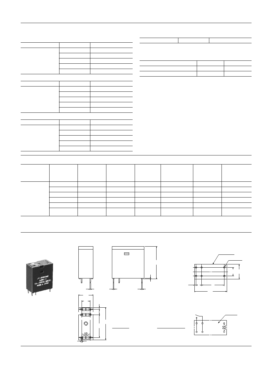
7.5
.295
Relay outline
20
.787
5
.179
1.45
.057
28.6
1.126
12.8
.504
6-1.3 DIA.
6-.051 DIA.
Top view
4
4
6
6
1
8