
360
JS-M RELAYS
Automotive Ultra-Miniature
Power Relay
16.4
.646
16
.630
22
.866
mm
inch
FEATURES
∑ Low pick-up voltage for high ambient use
∑ Sealed construction
∑ Ultra-miniature size with universal footprint
∑ Usable at high temperature: 85
∞
C
185
∞
F
SPECIFICATIONS
Contact
* Measured after operating 5 times at the rated load
Coil
Contact rating
Characteristics
Remarks
* Specifications will vary with foreign standards certification ratings.
*
1
Measurement at same location as "Intial breakdown voltage"section
*
2
Detection current: 10mA
*
3
Excluding contact bounce time
*
4
Half-wave pulse of sine wave: 11ms; detection time: 10
µ
s
*
5
Half-wave pulse of sine wave: 6ms
*
6
Detection time: 10
µ
s
*
7
Refer to 5. Conditions for operation, transport and storage mentioned in
AMBIENT ENVIRONMENT (Page 61)
Standard type
High capacity
type
Arrangement
1 Form A, 1 Form C
Contact material
Silver alloy
Initial contact resistance, max.*
(By voltage drop 6 V DC 1 A)
200 m
100 m
Initial voltage drop
Max. 0.2 V (at 10 A 12 V DC)
Rating
Nominal switching
capacity
10 A 16 V DC
(resistive)
15 A 16 V DC
(resistive)
Max. switching power
160 W
Max. switching voltage
16 V DC
Max. switching current
10 A
15 A
(10 A max. at
85
∞
C)
Expected
life (min.
ope.)
Mechanical life
(at 180 cpm)
10
7
Electrical
Resistive
10
5
N.O.: 10
5
N.C.: 5
◊
10
4
Nominal operating power
640 mW
Load
Standard type
High capacity type
Form A
Form C
Form A
Form C
N.O.
N.C.
N.O.
N.C.
Max. carry current
15 A
15 A
15 A
15 A
15 A
15 A
Max. make current
25 A
25 A
10 A
50 A
50 A
15 A
Max. break current
10 A
10 A
10 A
15 A
15 A
15 A
Max. operating speed
(at rated load)
15 cps.
Initial insulation resistance*
1
Min. 100 M
(at 500 V DC)
Initial
breakdown
voltage*
2
Between open
contacts
750 Vrms for 1 min.
Between
contacts and coil
1,500 Vrms for 1 min.
Operate time*
3
(at nominal voltage)
Approx. 10 ms
Release time (without diode)*
3
(at nominal voltage)
Approx. 10 ms
Shock
resistance
Functional*
4
Min. 98 m/s
2
{10 G}
Destructive*
5
Min. 980 m/s
2
{100 G}
Vibration
resistance
Functional*
6
Approx. 98 m/s
2
{10 G}, 10 to 55 Hz
at double amplitude of 1.6 mm
Destructive
Approx. 117.6 m/s
2
{12 G}, 10 to 55 Hz
at double amplitude of 2 mm
Conditions for
operation, trans-
port and storage*
7
(Not freezing and
condensing at low
temperature)
Ambient
temp.
≠40
∞
C to +85
∞
C
≠40
∞
F to +185
∞
F
Humidity
5 to 85% R.H.
Unit weight
Approx. 12 g
.423 oz
TYPICAL APPLICATIONS
∑ Automotive:
Power-window, car antenna, door lock, intermittent wiper, interior lighting, power seat,
power sunroof, car stereo power antenna, etc.
ORDERING INFORMATION
Ex. JSM
Contact arrangement
Note: Standard packing: Carton: 100 pcs. Case: 500 pcs.
1a: 1 Form A
1: 1 Form C
Nil: Sealed construction
F: Flux-resistant type
4: Standard type (10 A)
5: High capacity type (15 A)
9, 12 V
Protective construction
Coil voltage (DC)
Contact material
1a
F
12V
4

JS-M
361
TYPES AND COIL DATA
(at 20
∞
C
68
∞
F
)
DIMENSIONS
Contact
arrange-
ment
Coil
voltage,
V DC
Standard type (10 A)
High capacity type (15 A)
Nominal
voltage,
V DC
Pick-up
voltage,
V DC
(max.)
Drop-out
voltage,
V DC
(min.)
Coil
resistance
(
±
10%)
Nominal
operating
current,
mA
(
±
10%)
Nominal
operating
power,
mW
Max.
allowable
voltage,
V DC
(at 80
∞
C
176
∞
F
)
Sealed type
Flux-resistant
type
Sealed type
Flux-resistant
type
1 Form A
9
JSM1a-9V-4
JSM1aF-9V-4
JSM1a-9V-5
JSM1aF-9V-5
9
4.7
0.7
126
71.4
640
12
12
JSM1a-12V-4
JSM1aF-12V-4 JSM1a-12V-5
JSM1aF-12V-5
12
6.3
0.9
225
53.3
640
16
1 Form C
9
JSM1-9V-4
JSM1F-9V-4
JSM1-9V-5
JSM1F-9V-5
9
4.7
0.7
126
71.4
640
12
12
JSM1-12V-4
JSM1F-12V-4
JSM1-12V-5
JSM1F-12V-5
12
6.3
0.9
225
53.3
640
16
Note: Terminal No. 4 is only for
1 Form C type
mm
inch
General tolerance:
±
0.3
±
.012
16
.630
0.4
.016
3.9
.154
0.8
.031
5
4 N.C.
1
2
3 N.O.
0.8
.031
0.24
.009
12.2
.480
16
.630
12
.472
0.4
.016
0.4
.016
22
.866
2.3
.091
1.2
.047
2
.079
Schematic (Bottom view)
1a
1c
PC board pattern (Copper-side view)
1a
1c
Tolerance:
±
0.1
±
.004
N.O.
COM
COIL
N.O.
N.C.
COM
COIL
12
.472
4-1.3 dia.
4-.051 dia.
12.2
.480
2
.079
12
.472
5-1.3 dia.
5-.051 dia.
12.2
.480
2
.079
REFERENCE DATA
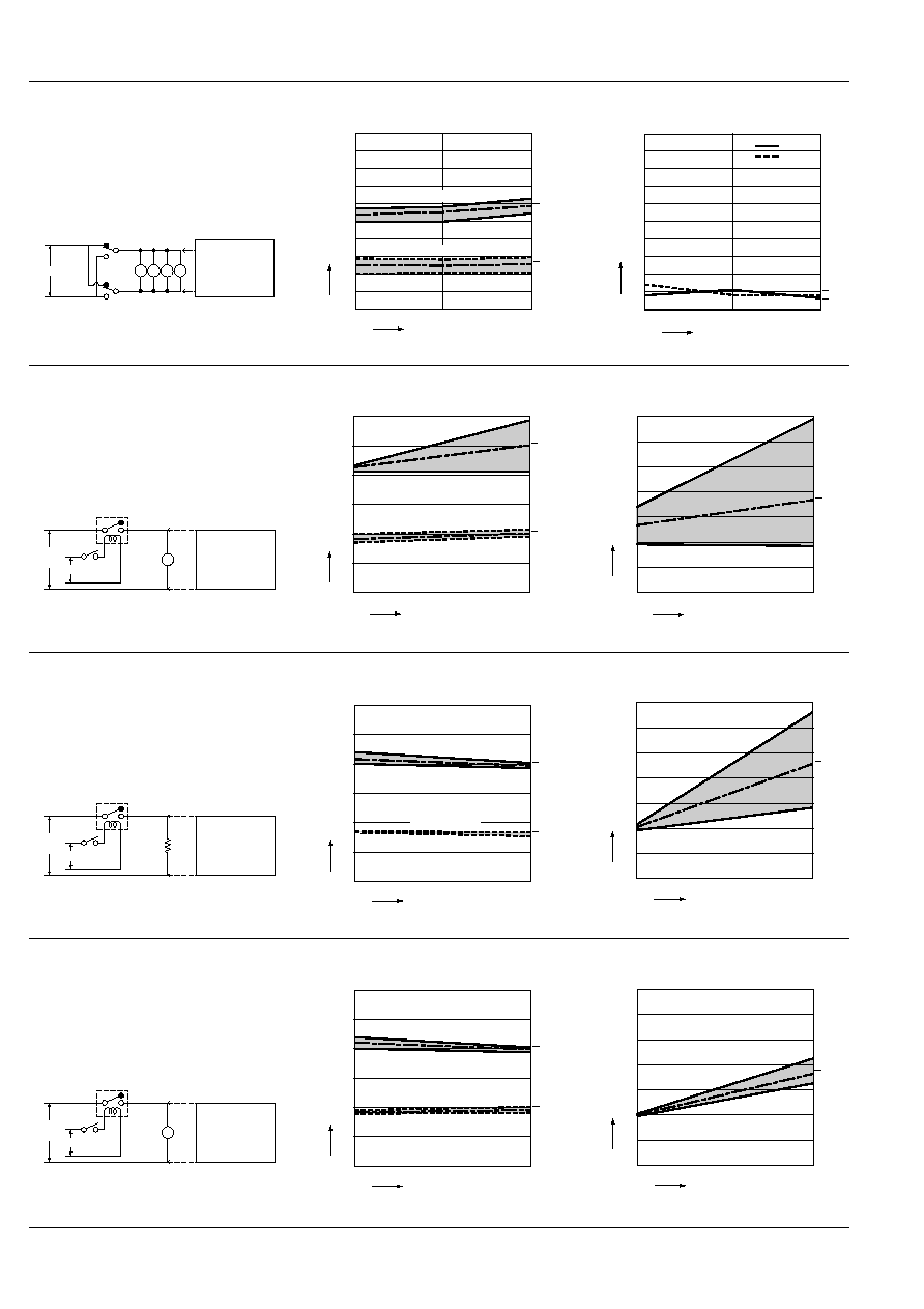
1-(1) Electrical life test (Resistive)
Tested sample: JSM-12V-4, 3 pcs.
Condition: 10 A 16 V DC resistive load, 20 cpm
Ambient temperature: 25
∞
C
77
∞
F
Circuit
Change of pick-up and drop-out voltage
Change of contact resistance
16 V
DC
+
≠
12 V DC
Detection circuit
Contact welding:
Min. 0.5 sec.
Mis-contacting:
After 0.2 sec.
10
0
1
2
3
4
5
6
Pick-up/drop-out voltage, V
No. of operations,
◊
10
4
Drop-out voltage
Pick-up voltage
Max.
Max.
Min.
Min.
x
x
10
0
2
4
6
8
10
12
14
x
Contact resistance, m
No. of operations,
◊
10
4
N.O. side
Max.
Min.
1-(2) Electrical life test
(Power window motor load)
Tested sample: JSM1-12V-4, 4 pcs.
Load: DC 14 V
(1) Max. 14.8 A (Inrush) Max. 14.2 A (Break)
(2) Max. 20.3 A (Inrush) Max. 20.0 A (Break)
(3) Max. 16.2 A (Inrush) Max. 11.6 A (Break)
Switching frequency: 3 cycle/min. (ON:OFF = 1:9 s)
Ambient temperature: (1) 85
∞
C
185
∞
F
;
(2) ≠40
∞
C
≠40
∞
F
; (3) 35
∞
C
95
∞
F
Tested cycle: (1) 2
◊
10
4
cycle
®
(2) 2 x 10
4
cycle
®
(3) 11
◊
10
4
cycle (Total 15
◊
10
4
cycles)
Circuit
Change of pick-up and drop-out voltage
Change of contact resistance
14 V DC
+
≠
Contact welding
detection and
Mis-contacting
detection circuit
M
M
Ry1
Ry2
~
Drop-out voltage
Pick-up voltage
Pick-up/drop-out voltage, V
x
x
Max.
Max.
Min.
Min.
15
0
1
2
3
4
5
6
7
8
9
10
No. of operations,
◊
10
4
2
4
N.C. side
N.O. side
0
10
20
30
40
50
60
70
80
90
100
x
x
Contact resistance, m
No. of operations,
◊
10
4
2
4
15
JS-M
362
1-(3) Electrical life test (Door lock motor load)
Tested sample: JSM1-12V-4, 10 pcs.
Load: DC 16 V Max. 17.7 A, Min. 15.2 A
Switching frequency: 6 cycles/min.
(ON:OFF = 0.5:0.5 s)
Ambient temperature: 30
∞
C
86
∞
F
Tested cycle: 4
◊
10
4
cycles
Circuit
Change of pick-up and drop-out voltage
Change of contact resistance
16 V DC
+
≠
Contact welding
detection and
Mis-contacting
detection circuit
M
M
M
M
2
4
0
1
2
3
4
5
6
7
8
9
10
No. of operations,
◊
10
4
Drop-out voltage
Pick-up voltage
x
x
Max.
Max.
Min.
Min.
Pick-up/drop-out voltage, V
30
N.C. side
N.O. side
2
4
0
10
20
40
50
60
70
80
90
100
Contact resistance, m
No. of operations,
◊
10
4
x
x
1-(4) Electrical life test
Tested sample: JSM1-12V-4, 3 pcs.
Load: 16 V DC 25 A/5 A motor load
Switching frequency: 6 cycles
(ON:OFF = 1:9 s)
Ambient temperature: 27
∞
C
81
∞
F
Circuit
Change of pick-up and drop-out voltage
Change of contact resistance
16 V
DC
+
≠
12 V DC
Detection circuit
Contact welding:
Min. 0.5 s
Mis-contacting:
After 0.2 s
M
10
0
1
2
3
4
5
6
Pick-up/drop-out voltage, V
No. of operations,
◊
10
4
Drop-out voltage
Pick-up voltage
x
x
Max.
Max.
Min.
Min.
Min.
10
0
2
4
6
8
10
12
14
Contact resistance, m
No. of operations,
◊
10
4
N.O. side
x
Max.
1-(5) Electrical life test
Tested sample: JSM1-12V-5, 4 pcs.
Load: 16 V DC 15 A (resistive)
Switching frequency: 20 cpm
Ambient temperature: 25
∞
C
77
∞
F
Circuit
Change of pick-up and drop-out voltage
Change of contact resistance
16 V
DC
+
≠
12 V DC
Detection circuit
Contact welding:
Min. 0.5 sec.
Mis-contacting:
After 0.2 sec.
10
0
1
2
3
4
5
6
Pick-up/drop-out voltage, V
No. of operations,
◊
10
4
Drop-out voltage
Pick-up voltage
x
Max.
Min.
x
Max.
Min.
10
0
2
4
6
8
10
12
14
Contact resistance, m
No. of operations,
◊
10
4
N.O. side
x
Max.
Min.
1-(6) Electrical life test
Tested sample: JSM1-12V-5, 3 pcs.
Load: 16 V DC 50 A/10 A motor load
Switching frequency: 6 cycles
(ON:OFF = 1:9 s)
Ambient temperature: 27
∞
C
81
∞
F
Circuit
Change of pick-up and drop-out voltage
Change of contact resistance
16 V
DC
+
≠
12 V DC
Detection circuit
Contact welding:
Min. 0.5 s
Mis-contacting:
After 0.2 s
M
10
0
1
2
3
4
5
6
Pick-up/drop-out voltage, V
No. of operations,
◊
10
4
Drop-out voltage
Pick-up voltage
x
Max.
x
Max.
Min.
Min.
10
0
2
4
6
8
10
12
14
Contact resistance, m
No. of operations,
◊
10
4
x
Max.
Min.
N.O. side
JS-M
363
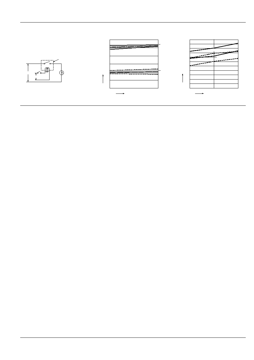
1-(7) Electrical life test (Lamp load)
Tested sample: JSM1a-12V-5, 4 pcs.
Load: 9.6A Steady, Inrush 55.2A,
14.5V DC (Lamp load)
Operating frequency: ON 1s, OFF 2s
Circuit
Contact welding: 0 time
Miscontact: 0 time
2. Temperature rise
Tested sample: JSM1-12V-4 & -5, 5 pcs.
Measured portion: Inside the coil
Tested sample
14.5V DC
DC12V
0
2
1
3
4
5
6
0
15
Pick-up voltage
Drop-out voltage
Pick-up/drop-out voltage, V
x
x
Max.
Max.
Min.
Min.
No. of operations,
◊
10
4
Temperature rise,
∞
C
Coil applied voltage, V
12
14
16
0
10
20
30
40
50
60
70
80
90
100
110
15 A at 25
∞
C
77
∞
F
15 A at 85
∞
C
185
∞
F
10 A at 85
∞
C
185
∞
F
10 A at 25
∞
C
77
∞
F
For Cautions for use, see Relay Technical Information (Page 48 to 76).
9/1/2000
All Rights Reserved, © Copyright Matsushita Electric Works, Ltd.
Go To Online Catalog