PLEASE NOTE:
PLEASE NOTE:
PLEASE NOTE:
PLEASE NOTE:
PLEASE NOTE:
The following part numbers
The following part numbers
The following part numbers
The following part numbers
The following part numbers
from this datasheet are not
from this datasheet are not
from this datasheet are not
from this datasheet are not
from this datasheet are not
recommended for new design.
recommended for new design.
recommended for new design.
recommended for new design.
recommended for new design.
Please call sales office for
Please call sales office for
Please call sales office for
Please call sales office for
Please call sales office for
details:
details:
details:
details:
details:
NE68539R
NE68539R
NE68539R
NE68539R
NE68539R
PART NUMBER
1
NE68518
NE68519
NE68530
NE68533
NE68539/39R
EIAJ
2
REGISTERED NUMBER
2SC5015
2SC5010
2SC4959
2SC4955
2SC4957
PACKAGE OUTLINE
18
19
30
33
39
SYMBOLS PARAMETERS AND CONDITIONS UNITS MIN TYP MAX MIN TYP MAX MIN TYP MAX MIN TYP MAX MIN TYP MAX
f
T
Gain Bandwidth Product at
V
CE
= 3V, I
C
= 10 mA, f = 2.0 GHz
GHz
12
12
12
12
12
NF
MIN
Minimum Noise Figure at
V
CE
= 3 V, I
C
= 3 mA, f = 2.0 GHz
dB
1.5
2.5
1.5
2.5
1.5
2.5
1.5
2.5
1.5
2.5
G
NF
Associated Gain at
V
CE
= 3V, I
C
= 3 mA, f = 2.0 GHz
dB
8.5
7.5
7
7
7.5
MAG
Maximum Available Gain at
V
CE
= 3 V, I
C
= 10 mA, f = 2.0 GHz
dB
12
11
10
10.5
11
|S
21E
|
2
Insertion Power Gain at
V
CE
= 3V, I
C
=10 mA, f = 2.0 GHz
dB
9
11
7
9
7
8.5
7
8
9
10
h
FE
Forward Current Gain
3
at
V
CE
= 3 V, I
C
= 10 mA
75 110 150
75
110 150
75
110 150
75
110 150
75
110 150
I
CBO
Collector Cutoff Current
at V
CB
= 5 V, I
E
= 0 mA
µ
A
0.1
0.1
0.1
0.1
0.1
I
EBO
Emitter Cutoff Current
at V
EB
= 1 V, I
C
= 0 mA
µ
A
0.1
0.1
0.1
0.1
0.1
C
RE4
Feedback Capacitance at
V
CB
= 3 V, I
E
= 0 mA, f = 1 MHz
pF
0.3
0.5
0.4
0.7
0.4
0.7
0.4
0.7
0.3
0.5
P
T
Total Power Dissipation
mW
150
125
150
180
180
R
TH(J-A)
Thermal Resistance
(Junction to Ambient)
∞
C/W
833
1000
833
620
620
R
TH(J-C)
Thermal Resistance(Junction to Case)
∞
C/W
200
200
200
200
200
SURFACE MOUNT NPN SILICON
HIGH FREQUENCY TRANSISTOR
NE685
SERIES
FEATURES
∑ LOW COST
∑ SMALL AND ULTRA SMALL SIZE PACKAGES
∑ LOW VOLTAGE/LOW CURRENT OPERATION
∑ HIGH GAIN BANDWIDTH PRODUCT: f
T
of 12 GHz
∑ NOISE FIGURES OF 1.5 dB AT 2.0 GHZ
30 (SOT 323 STYLE)
ELECTRICAL CHARACTERISTICS
(T
A
= 25
∞
C)
18 (SOT 343 STYLE)
39 (SOT 143 STYLE)
33 (SOT 23 STYLE)
19 (3 PIN ULTRA SUPER
MINI MOLD)
39R (SOT 143R STYLE)
DESCRIPTION
NEC's family of high frequency, low cost, surface mount
devices are well suited for portable wireless communications
and cellular radio applications.
The NE685 series of high f
T
(12 GHz) devices is suitable for
very low voltage/low current, low noise applications. These
products are ideal for applications up to 2.4 GHz where low
cost, high gain, low voltage, and low current are prime con-
cerns.
Notes: 1. Precaution: Devices are ESD sensitive. Use proper handling procedures.
2. Electronic Industrial Association of Japan.
3. Pulsed measurement, PW
350
µ
s, duty cycle
2%.
4. The emitter terminal should be connected to the ground terminal
of the 3 terminal capacitance bridge.
California Eastern Laboratories

NE68518, NE68530
D.C. POWER DERATING CURVE
200
100
0
0
50
100
150
INFINITE
HEAT SINK
FREE AIR
114
180
Ambient Temperature, T
A
(C
∞
)
Total Power Dissipation, P
T
(mW)
200
100
0
0
100
150
125
180
50
50
150
114
FREE AIR
INFINITE
HEAT SINK
Ambient Temperature, T
A
(C
∞
)
Total Power Dissipation, P
T
(mW)
NE68519
D.C. POWER DERATING CURVE
1 2 5 10 20 50
5
4
3
2
1
0
V
CE
= 3 V
f = 2 GHz
V
CE
= 3 V
I
C
= 10 mA
MAG
|S
21E
|
2
0.1 0.2 0.5 1.0 2.0 5.0
50
40
30
20
10
0
38.4 114
0 50 100 150
0
100
180
200
FREE AIR
INFINITE
HEAT SINK
Total Power Dissipation, P
T
(mW)
Noise Figure, N
F
(dB)
Frequency, f (GHz)
NE68533, NE68539
D.C. POWER DERATING CURVE
1 2 5 10 20 50
0
2
4
6
8
10
12
V
CE
= 3 V
f = 2 GHz
INSERTION GAIN vs.
COLLECTOR CURRENT
Collector Current, I
C
(mA)
Ambient Temperature, T
A
(
∞
C)
Insertion Gain, |S21
E
|
2
(dB)
Collector Current, I
C
(mA)
Insertion Gain, |S21
E
|
2
(dB)
Maximum Available Gain, MAG (dB)
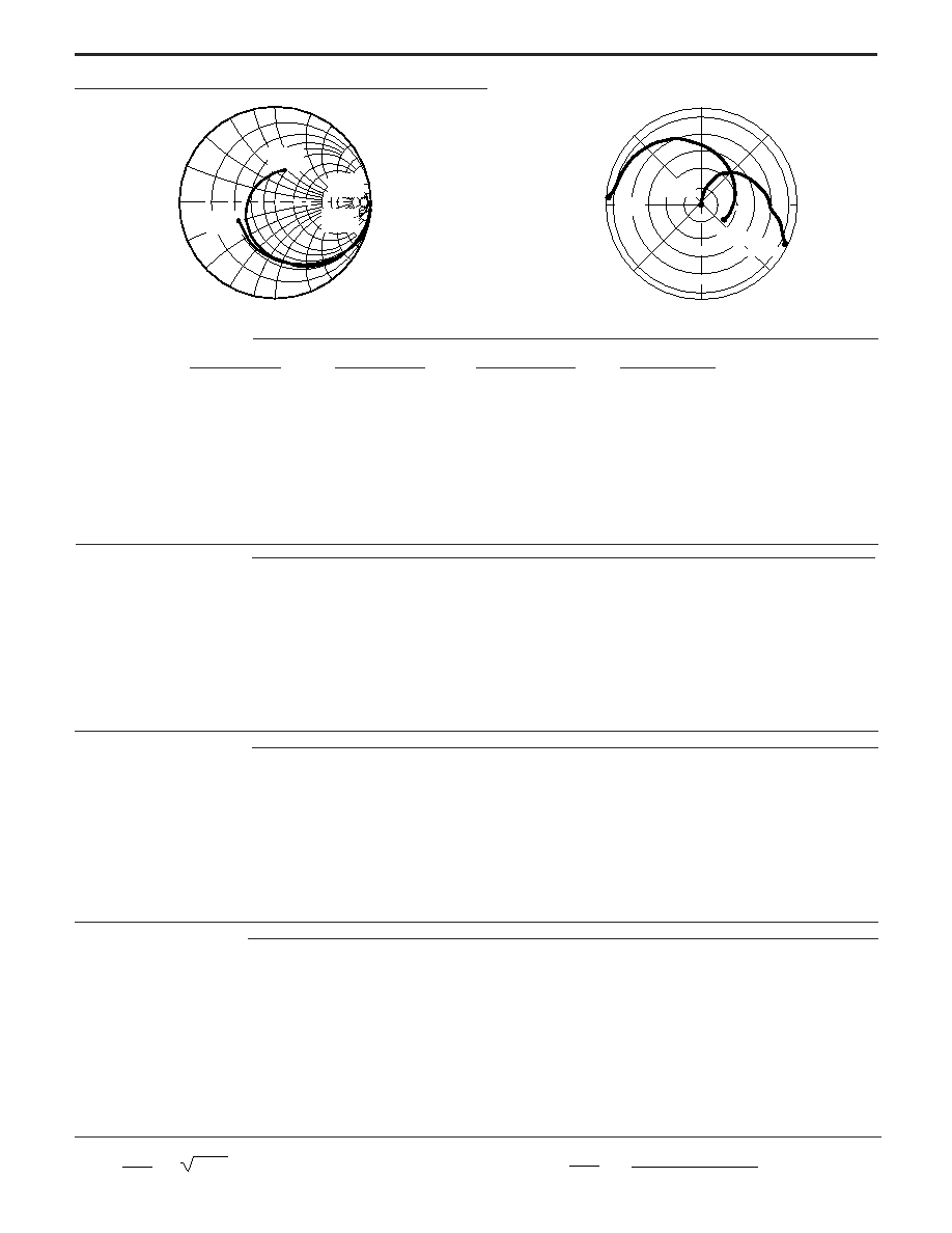
TYPICAL PERFORMANCE CURVES
(TA = 25
∞
C)
NOISE FIGURE
vs. COLLECTOR CURRENT
FORWARD INSERTION GAIN
AND MAXIMUM AVAILABLE GAIN
vs. FREQUENCY
NE685 SERIES