 | –≠–ª–µ–∫—Ç—Ä–æ–Ω–Ω—ã–π –∫–æ–º–ø–æ–Ω–µ–Ω—Ç: CLC450 | –°–∫–∞—á–∞—Ç—å:  PDF PDF  ZIP ZIP |

Features
s
100mA output current
s
1.5mA supply current
s
100MHz bandwidth (A
v
= +2)
s
-79/-75dBc HD2/HD3 (1MHz)
s
20ns settling to 0.05%
s
280V/
µ
s slew rate
s
Stable for capacitive loads up to 1000pf
s
Single 5V to ±5V supplies
s
Available in Tiny SOT23-5 package
Applications
s
Coaxial cable driver
s
Twisted pair driver
s
Transformer/Coil Driver
s
High capacitive load driver
s
Video line driver
s
Portable/battery-powered applications
s
A/D driver
V
EE
+
-
CLC450
1k
0.1
µ
F
6.8
µ
F
V
o
V
in
+5V
3
2
4
7
6
+
1k
5k
5k
0.1
µ
F
10m of 75
Coaxial Cable
75
0.1
µ
F
75
0.1
µ
F
Typical Application
Single Supply Cable Driver
Pinout
DIP & SOIC
General Description
The CLC450 has a new output stage that delivers high output
drive current (100mA), but consumes minimal quiescent supply
current (1.5mA) from a single 5V supply. Its current feedback
architecture, fabricated in an advanced complementary bipolar
process, maintains consistent performance over a wide range of
gains and signal levels, and has a linear-phase response up to
one half of the -3dB frequency.
The CLC450 offers superior dynamic performance with a
100MHz small-signal bandwidth, 280V/
µ
s slew rate and 6.1ns
rise/fall times (2V
step
). The combination of low quiescent power,
high output current drive, and high-speed performance make
the CLC450 well suited for many battery-powered personal
communication/computing systems.
The ability to drive low-impedance, highly capacitive loads,
makes the CLC450 ideal for single ended cable applications. It
also drives low impedance loads with minimum distortion. The
CLC450 will drive a 100
load with only -75/-64dBc second/third
harmonic distortion (A
v
= +2, V
out
= 2V
pp
, f = 1MHz). With a 25
load, and the same conditions, it produces only -70/-60dBc sec-
ond/third harmonic distortion. It is also optimized for driving high
currents into single-ended transformers and coils.
When driving the input of high-resolution A/D converters, the
CLC450 provides excellent -79/-75dBc second/third harmonic
distortion (A
v
= +2, V
out
= 2V
pp
, f = 1MHz, R
L
= 1k
) and fast
settling time.
Available in SOT23-5, the CLC450 is ideal for applications where
space is critical.
Maximum Output Voltage vs. R
L
Output Voltage (V
pp
)
R
L
(
)
1
2
3
4
5
6
7
8
9
10
10
100
1000
V
s
= +5V
V
CC
=
±
5V
CLC450
Single Supply, Low-Power, High Output,
Current Feedback Amplifier
N
June 1999
CLC450
Single Suppl
y
,
Lo
w-P
o
wer
,
High Output,
Current Feedbac
k Amp
Response After 10m of Cable
100mV/div
20ns/div
V
in
= 10MHz, 0.5V
pp
V
inv
V
CC
V
EE
V
o
V
non-inv
Pinout
SOT23-5
© 1999 National Semiconductor Corporation
http://www.national.com
Printed in the U.S.A.

http://www.national.com
2
PARAMETERS
CONDITIONS
TYP
MIN/MAX RATINGS
UNITS
NOTES
Ambient Temperature
CLC450AJ
+25∞C
+25∞C
0 to 70∞C
-40 to 85∞C
FREQUENCY DOMAIN RESPONSE
-3dB bandwidth
V
o
< 0.5V
pp
100
85
75
70
MHz
V
o
< 2.0V
pp
75
60
55
50
MHz
-0.1dB bandwidth
V
o
< 0.5V
pp
30
25
20
20
MHz
gain peaking
<200MHz, V
o
= 0.5V
pp
0
0.5
0.9
1.0
dB
gain rolloff
<30MHz, V
o
= 0.5V
pp
0.1
0.3
0.4
0.5
dB
linear phase deviation
<30MHz, V
o
= 0.5V
pp
0.2
0.4
0.5
0.5
deg
TIME DOMAIN RESPONSE
rise and fall time
2V step
6.1
8.5
9.2
10.0
ns
settling time to 0.05%
1V step
20
30
50
80
ns
overshoot
2V step
16
20
22
22
%
slew rate
2V step
280
200
185
170
V/
µ
s
DISTORTION AND NOISE RESPONSE
2
nd
harmonic distortion
2V
pp
, 1MHz
-75
≠
≠
≠
dBc
2V
pp
, 1MHz; R
L
= 1k
-79
≠
≠
≠
dBc
2V
pp
, 5MHz
-62
-58
-57
-56
dBc
3
rd
harmonic distortion
2V
pp
, 1MHz
-64
≠
≠
≠
dBc
2V
pp
, 1MHz; R
L
= 1k
-75
≠
≠
≠
dBc
2V
pp
, 5MHz
-52
-48
-46
-46
dBc
equivalent input noise
voltage (e
ni
)
>1MHz
3.0
3.7
4.0
4.0
nV/
Hz
non-inverting current (i
bn
)
>1MHz
6.9
9
10
10
pA/
Hz
inverting current (i
bi
)
>1MHz
8.5
11
12
12
pA/
Hz
STATIC DC PERFORMANCE
input offset voltage
1
4
5
6
mV
A
average drift
7
≠
15
15
µ
V/∞C
input bias current (non-inverting)
5
12
15
16
µ
A
A
average drift
25
≠
60
60
nA/∞C
input bias current (inverting)
3
10
12
13
µ
A
A
average drift
10
≠
20
20
nA/∞C
power supply rejection ratio
DC
54
50
48
48
dB
common-mode rejection ratio
DC
51
47
45
45
dB
supply current
R
L
=
1.5
1.7
1.8
1.8
mA
A
MISCELLANEOUS PERFORMANCE
input resistance (non-inverting)
0.46
0.37
0.33
0.33
M
input capacitance (non-inverting)
1.5
2.3
2.3
2.3
pF
input voltage range, High
4.2
4.1
4.1
4.0
V
input voltage range, Low
0.8
0.9
0.9
1.0
V
output voltage range, High
R
L
= 100
4.0
3.9
3.9
3.8
V
output voltage range, Low
R
L
= 100
1.0
1.1
1.1
1.2
V
output voltage range, High
R
L
=
4.1
4.0
4.0
3.9
V
output voltage range, Low
R
L
=
0.9
1.0
1.0
1.1
V
output current
100
80
65
40
mA
B
output resistance, closed loop
DC
55
90
90
120
m
Min/max ratings are based on product characterization and simulation. Individual parameters are tested as noted. Outgoing quality levels are
determined from tested parameters.
+5V Electrical Characteristics
(A
v
= +2, R
f
= 1k
, R
L
= 100
, V
s
= +5V
1
, V
cm
= V
EE
+ (V
s
/2), R
L
tied to V
cm
, unless specified)
Absolute Maximum Ratings
supply voltage (V
CC
- V
EE
)
+14V
output current (see note C)
140mA
common-mode input voltage
V
EE
to V
CC
maximum junction temperature
+150∞C
storage temperature range
-65∞C to +150∞C
lead temperature (soldering 10 sec)
+300∞C
ESD rating (human body model)
500V
Notes
A) J-level: spec is 100% tested at +25∞C.
B) The short circuit current can exceed the maximum safe
output current.
1) V
s
= V
CC
- V
EE
Reliability Information
Transistor Count
49
MTBF (based on limited test data)
31Mhr
3
http://www.national.com
PARAMETERS
CONDITIONS
TYP
GUARANTEED MIN/MAX
UNITS
NOTES
Ambient Temperature
CLC450AJ
+25∞C
+25∞C
0 to 70∞C
-40 to 85∞C
FREQUENCY DOMAIN RESPONSE
-3dB bandwidth
V
o
< 1.0V
pp
135
115
105
100
MHz
V
o
< 4.0V
pp
55
45
42
40
MHz
-0.1dB bandwidth
V
o
< 1.0V
pp
40
30
25
25
MHz
gain peaking
<200MHz, V
o
= 1.0V
pp
0
0.5
0.9
1.0
dB
gain rolloff
<30MHz, V
o
= 1.0V
pp
0.1
0.3
0.4
0.5
dB
linear phase deviation
<30MHz, V
o
= 1.0V
pp
0.1
0.3
0.4
0.4
deg
differential gain
NTSC, R
L
=150
0.03
≠
≠
≠
%
differential phase
NTSC, R
L
=150
0.3
≠
≠
≠
deg
TIME DOMAIN RESPONSE
rise and fall time
2V step
4.4
5.8
6.2
6.8
ns
settling time to 0.05%
2V step
15
25
40
60
ns
overshoot
2V step
15
20
22
22
%
slew rate
2V step
370
280
260
240
V/
µ
s
DISTORTION AND NOISE RESPONSE
2
nd
harmonic distortion
2V
pp
, 1MHz
-86
≠
≠
≠
dBc
2V
pp
, 1MHz; R
L
= 1k
-85
≠
≠
≠
dBc
2V
pp
, 5MHz
-68
-64
-61
-60
dBc
3
rd
harmonic distortion
2V
pp
, 1MHz
-65
≠
≠
≠
dBc
2V
pp
, 1MHz; R
L
= 1k
-74
≠
≠
≠
dBc
2V
pp
, 5MHz
-52
-48
-46
-46
dBc
equivalent input noise
voltage (e
ni
)
>1MHz
3.0
3.7
4.0
4.0
nV/
Hz
non-inverting current (i
bn
)
>1MHz
6.9
9
10
10
pA/
Hz
inverting current (i
bi
)
>1MHz
8.5
11
12
12
pA/
Hz
STATIC DC PERFORMANCE
input offset voltage
2
6
7
8
mV
average drift
8
≠
20
20
µ
V/∞C
input bias current (non-inverting)
5
12
16
17
µ
A
average drift
40
≠
70
70
nA/∞C
input bias current (inverting)
5
13
15
16
µ
A
average drift
20
≠
45
45
nA/∞C
power supply rejection ratio
DC
56
51
49
49
dB
common-mode rejection ratio
DC
53
48
46
46
dB
supply current
R
L
=
1.6
1.9
2.0
2.0
mA
MISCELLANEOUS PERFORMANCE
input resistance (non-inverting)
0.62
0.50
0.45
0.45
M
input capacitance (non-inverting)
1.2
1.8
1.8
1.8
pF
common-mode input range
±4.2
±4.1
±4.1
±4.0
V
output voltage range
R
L
= 100
±3.8
±3.6
±3.6
±3.5
V
output voltage range
R
L
=
±4.0
±3.8
±3.8
±3.7
V
output current
130
100
80
50
mA
B
output resistance, closed loop
DC
40
70
70
90
m
±5V Electrical Characteristics
(A
v
= +2, R
f
= 1k
, R
L
= 100
, V
CC
= ±5V, unless specified)
Notes
B) The short circuit current can exceed the maximum safe
output current.
Ordering Information
Model
Temperature Range
Description
CLC450AJP
-40
∞
C to +85
∞
C
8-pin PDIP
CLC450AJE
-40
∞
C to +85
∞
C
8-pin SOIC
CLC450AJM5
-40
∞
C to +85
∞
C
5-pin SOT
CLC450ALC
-40
∞
C to +85
∞
C
dice
Package Thermal Resistance
Package
JC
JA
Plastic (AJP)
115
∞
C/W
125
∞
C/W
Surface Mount (AJE)
130
∞
C/W
150
∞
C/W
Surface Mount (AJM5)
140
∞
C/W
210
∞
C/W
Dice (ALC)
25
∞
C/W
≠
http://www.national.com
4
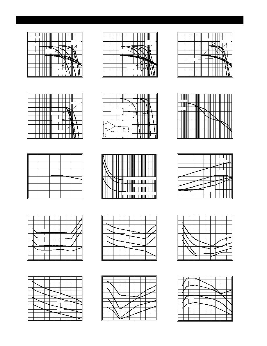
+5V Typical Performance
(A
v
= +2, R
f
= 1k
, R
L
= 100
, V
s
= +5V
1
, V
cm
= V
EE
+ (V
s
/2), R
L
tied to V
cm
, unless specified)
Non-Inverting Frequency Response
Normalized Magnitude (1dB/div)
Frequency (Hz)
1M
10M
100M
Phase (deg)
-90
0
-180
-450
-270
-360
Gain
Phase
V
o
= 1V
pp
A
v
= 2
R
f
= 845
A
v
= 1
R
f
= 1.1k
A
v
= 5
R
f
= 845
A
v
= 10
R
f
= 845
Inverting Frequency Response
Normalized Magnitude (1dB/div)
Frequency (Hz)
1M
10M
100M
Phase (deg)
-270
-180
-360
-630
-450
-540
Gain
Phase
V
o
= 1V
pp
A
v
= -2
R
f
= 866
A
v
= -1
R
f
= 1.1k
A
v
= -5
R
f
= 825
A
v
= -10
R
f
= 787
Frequency Response vs. R
L
Magnitude (1dB/div)
Frequency (Hz)
1M
10M
100M
Phase (deg)
-90
0
-180
-450
-270
-360
Gain
Phase
V
o
= 1V
pp
R
L
= 25
R
L
= 100
R
L
= 1k
Frequency Response vs. V
o
Magnitude (1dB/div)
Frequency (Hz)
1M
10M
100M
V
o
= 2V
pp
V
o
= 0.1V
pp
V
o
= 1V
pp
V
o
= 2.5V
pp
Frequency Response vs. C
L
Magnitude (1dB/div)
Frequency (Hz)
1M
10M
100M
V
o
= 1V
pp
C
L
= 10pF
R
s
= 46.4
C
L
= 100pF
R
s
= 20
C
L
= 1000pF
R
s
= 6.7
C
L
1k
R
s
+
-
1k
1k
Open Loop Transimpedance Gain, Z(s)
Magnitude (dB
)
Frequency (Hz)
1k
10k
100k
1M
10M
100M
Gain
Phase (deg)
0
45
90
135
180
225
40
60
80
100
120
140
Phase
Gain Flatness
Magnitude (0.05dB/div)
Frequency (MHz)
10
20
30
Equivalent Input Noise
Noise Voltage (nV/
Hz)
Frequency (Hz)
4
3.5
0.1k
1k
10k
100k
1M
10M
3
2.5
Non-Inverting Current 6.9pA/
Hz
Inverting Current 8.5pA/
Hz
Voltage 3.0nV/
Hz
Noise Current (pA/
Hz)
10
11
12
9
6
8
7
2nd & 3rd Harmonic Distortion
Distortion (dBc)
Frequency (Hz)
1M
10M
V
o
= 2V
pp
-90
-80
-70
-60
-50
-40
2nd
R
L
= 1k
2nd
R
L
= 100
3rd
R
L
= 100
3rd
R
L
= 1k
2nd Harmonic Distortion, R
L
= 25
Distortion (dBc)
Output Amplitude (V
pp
)
0
0.5
1
1.5
2
2.5
-80
-70
-60
-50
-40
-30
2MHz
5MHz
10MHz
1MHz
3rd Harmonic Distortion, R
L
= 25
Distortion (dBc)
Output Amplitude (V
pp
)
0
0.5
1
1.5
2
2.5
-70
-60
-50
-40
-30
-20
2MHz
5MHz
10MHz
1MHz
2nd Harmonic Distortion, R
L
= 100
Distortion (dBc)
Output Amplitude (V
pp
)
0
0.5
1
1.5
2
2.5
-90
-80
-70
-60
-50
-40
2MHz
5MHz
10MHz
1MHz
3rd Harmonic Distortion, R
L
= 100
Distortion (dBc)
Output Amplitude (V
pp
)
0
0.5
1
1.5
2
2.5
-70
-60
-50
-40
-30
2MHz
5MHz
10MHz
1MHz
2nd Harmonic Distortion, R
L
= 1k
Distortion (dBc)
Output Amplitude (V
pp
)
0
0.5
1
1.5
2
2.55
-90
-85
-80
-75
-70
-65
-60
-55
2MHz
5MHz
10MHz
1MHz
3rd Harmonic Distortion, R
L
= 1k
Distortion (dBc)
Output Amplitude (V
pp
)
0
0.5
1
1.5
2
2.5
-85
-80
-75
-70
-65
-60
-55
-50
2MHz
5MHz
10MHz
1MHz
5
http://www.national.com
+5V Typical Performance
(A
v
= +2, R
f
= 1k
, R
L
= 100
, V
s
= + 5V
1
, V
cm
= V
EE
+ (V
s
/2), R
L
tied to V
cm
, unless specified)
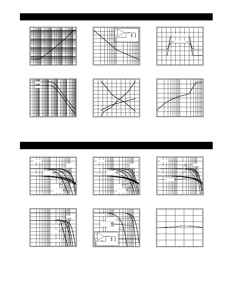
Closed Loop Output Resistance
Output Resistance (
)
Frequency (Hz)
10k
100k
1M
10M
100M
0.01
0.1
1
10
100
Recommended R
s
vs. C
L
R
s
(
)
C
L
(pF)
10
100
1000
0
10
20
30
40
50
C
L
1k
R
s
+
-
1k
1k
Large & Small Signal Pulse Response
Output Voltage (0.5V/div)
Time (20ns/div)
Large Signal
Small Signal
PSRR & CMRR
PSRR & CMRR (dB)
Frequency (Hz)
1k
10k
100M
0
10
20
30
40
50
60
100k
1M
10M
PSRR
CMRR
I
BI
, I
BN
, V
os
vs. Temperature
Offset Voltage V
os
(mV)
Temperature (
∞
C)
-100
-50
0
50
100
150
-1.1
I
BI
, I
BN
(
µ
A)
1
-1
2
-0.9
3
-0.8
4
-0.7
5
-0.6
6
I
BN
I
BI
V
os
Maximum Output Voltage vs. R
L
Output Voltage (V
pp
)
R
L
(
)
10
100
1000
1
1.5
2
2.5
3
3.5
4
4.5
5
±5V Typical Performance
(A
v
= +2, R
f
= 1k
, R
L
= 100
, V
CC
= ± 5V, unless specified)
Non-Inverting Frequency Response
Normalized Magnitude (1dB/div)
Frequency (Hz)
1M
10M
100M
Phase (deg)
-90
0
-180
-450
-270
-360
Gain
Phase
V
o
= 1V
pp
A
v
= +1
R
f
= 1.3k
A
v
= +2
R
f
= 845
A
v
= +5
R
f
= 825
A
v
= +10
R
f
= 845
Inverting Frequency Response
Normalized Magnitude (1dB/div)
Frequency (Hz)
1M
10M
100M
Phase (deg)
-270
-180
-360
-630
-450
-540
Gain
Phase
V
o
= 1V
pp
A
v
= -1
R
f
= 866
A
v
= -2
R
f
= 825
A
v
= -5
R
f
= 825
A
v
= -10
R
f
= 787
Frequency Response vs. R
L
Magnitude (1dB/div)
Frequency (Hz)
1M
10M
100M
Phase (deg)
-90
0
-180
-450
-270
-360
Gain
Phase
V
o
= 1V
pp
R
L
= 25
R
L
= 100
R
L
= 1k
Frequency Response vs. V
o
Magnitude (1dB/div)
Frequency (Hz)
1M
10M
100M
V
o
= 2V
pp
V
o
= 0.1V
pp
V
o
= 1V
pp
V
o
= 5V
pp
Frequency Response vs. C
L
Magnitude (1dB/div)
Frequency (Hz)
1M
10M
100M
V
o
= 1V
pp
C
L
= 10pF
R
s
= 68.1
C
L
= 100pF
R
s
= 17.4
C
L
= 1000pF
R
s
= 6.7
C
L
1k
R
s
+
-
1k
1k
Gain Flatness
Magnitude (0.05dB/div)
Frequency (MHz)
10
20
30