R
2
Long Barrel Inductive Prox
E2E2 3-Wire DC
Rugged Inductive Prox Sensors Meet
IP67 Requirements
H
Solid potted internal circuitry withstands
shocks and water washdown to IP67
H
Thick nickel-plated brass barrel has wrench
flats for easy installation
H
High visibility indicator
H
Connector and prewired versions
Ordering Information
J
PRE-WIRED SENSORS
Type
Size
Sensing distance
Output
Part number
yp
g
p
NO
NC
Shielded
M12
2 mm
NPN
E2E2-X2C1
E2E2-X2C2
2 mm
PNP
E2E2-X2B1
E2E2-X2B2
M18
5 mm
NPN
E2E2-X5C1
E2E2-X5C2
5 mm
PNP
E2E2-X5B1
E2E2-X5B2
M30
10 mm
NPN
E2E2-X10C1
E2E2-X10C2
10 mm
PNP
E2E2-X10B1
E2E2-X10B2
Unshielded
M12
5 mm
NPN
E2E2-X5MC1
E2E2-X5MC2
Unshielded
5 mm
PNP
E2E2-X5MB1
E2E2-X5MB2
M18
10 mm
NPN
E2E2-X10MC1
E2E2-X10MC2
10 mm
PNP
E2E2-X10MB1
E2E2-X10MB2
M30
NPN
E2E2-X18MC1
E2E2-X18MC2
18 mm
PNP
E2E2-X18MB1
E2E2-X18MB2
J
SENSORS WITH M12 CONNECTORS
Type
Size
Sensing distance
Output
Part number
yp
g
p
NO
NC
Shielded
M12
2 mm
NPN
E2E2-X2C1-M1
E2E2-X2C2-M1
2 mm
PNP
E2E2-X2B1-M1
E2E2-X2B2-M1
M18
5
NPN
E2E2-X5C1-M1
E2E2-X5C2-M1
5 mm
PNP
E2E2-X5B1-M1
E2E2-X5B2-M1
M30
10 mm
NPN
E2E2-X10C1-M1
E2E2-X10C2-M1
10 mm
PNP
E2E2-X10B1-M1
E2E2-X10B2-M1
Unshielded
M12
5
NPN
E2E2-X5MC1-M1
E2E2-X5MC2-M1
Unshielded
5 mm
PNP
E2E2-X5MB1-M1
E2E2-X5MB2-M1
M18
10 mm
NPN
E2E2-X10MC1-M1
E2E2-X10MC2-M1
10 mm
PNP
E2E2-X10MB1-M1
E2E2-X10MB2-M1
M30
NPN
E2E2-X18MC1-M1
E2E2-X18MC2-M1
18 mm
PNP
E2E2-X18MB1-M1
E2E2-X18MB2-M1
E2E2 3-Wire DC
E2E2 3-Wire DC
3
J
ACCESSORIES
Description
Part number
Mounting brackets
Fits M12 size sensors
Fits M18 size sensors
Fits M30 size sensors
Y92E-B12
Y92E-B18
Y92E-B30
Silicone rubber covers for shielded sensors
Fits M12 size sensors
Fits M18 size sensors
Fits M30 size sensors
Y92E-E12-2
Y92E-E18-2
Y92E-E30-2
Connector cordsets
See Y96E Connector Cordsets data sheet for details
J
REPLACEMENT PARTS
Description
Part number
Mounting hardware including one pair of
metal nuts and one washer
Fits M12 size sensors
Fits M18 size sensors
Fits M30 size sensors
M12-MHWS
M18-MHWS
M30-MHWS
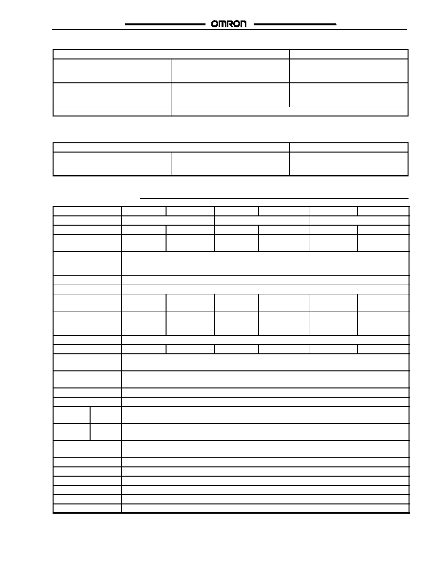
Specifications
Part number
E2E2-X2Cj/Bj
E2E2-X5MCj/Bj
E2E2-X5Cj/Bj
E2E2-X10MCj/Bj
E2E2-X10Cj/Bj
E2E2-X18MCj/Bj
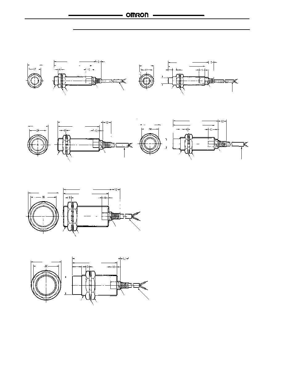
Size
M12
M18
M30
Type
Shielded
Unshielded
Shielded
Unshielded
Shielded
Unshielded
Sensing distance
2 mm (0.08 in)
±10%
5 mm (0.20 in)
±10%
5 mm (0.20 in)
±10%
10 mm (0.39 in)
±10%
10 mm (0.39 in)
±10%
18 mm (0.71 in)
±10%
Supply voltage
(operating voltage
range)
12 to 24 VDC, ripple (p-p): 10% max., (10 to 55 VDC)
Current consumption
13 mA max.
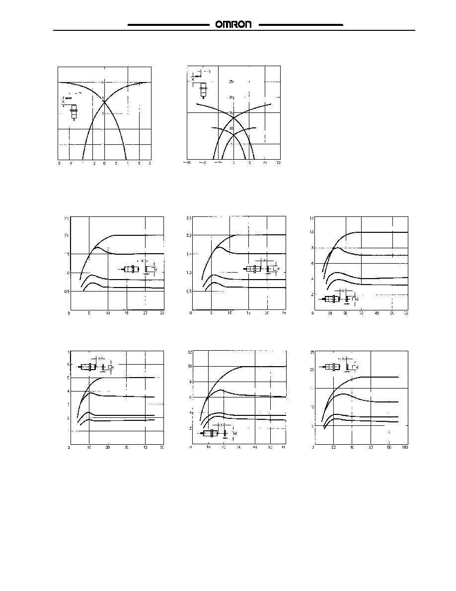
Sensing object
Magnetic metals (refer to Engineering Data for non-magnetic metals)
Setting distance
0 to 1.6 mm
(0 to 0.06 in)
0 to 4.0 mm
(0 to 0.16 in)
0 to 4.0 mm
(0 to 0.16 in)
0 to 8.0 mm
(0 to 0.31 in)
0 to 8.0 mm
(0 to 0.31 in)
0 to 14.0 mm
(0 to 0.55 in)
Standard object
(mild steel)
12 x 12 x
1 mm (0.47 x
0.47 x 0.04 in)
15 x 15 x 1 mm
(0.59 x 0.59 x
0.04 in)
18 x 18 x
1 mm (0.71 x
0.71 x 0.04 in)
30 x 30 x 1 mm
(1.18 x 1.18 x
0.04 in)
30 x 30 x 1 mm
(1.18 x 1.18 x
0.04 in)
54 x 54 x 1 mm
(2.13 x 2.13 x
0.04 in)
Differential travel
10% max. of sensing distance
Response frequency
1.5 kHz
0.4 kHz
0.6 kHz
0.2 kHz
0.4 kHz
0.1 kHz
Operation (with sensing
object approaching)
B1/C1 models: Load ON
B2/C2 models: Load OFF
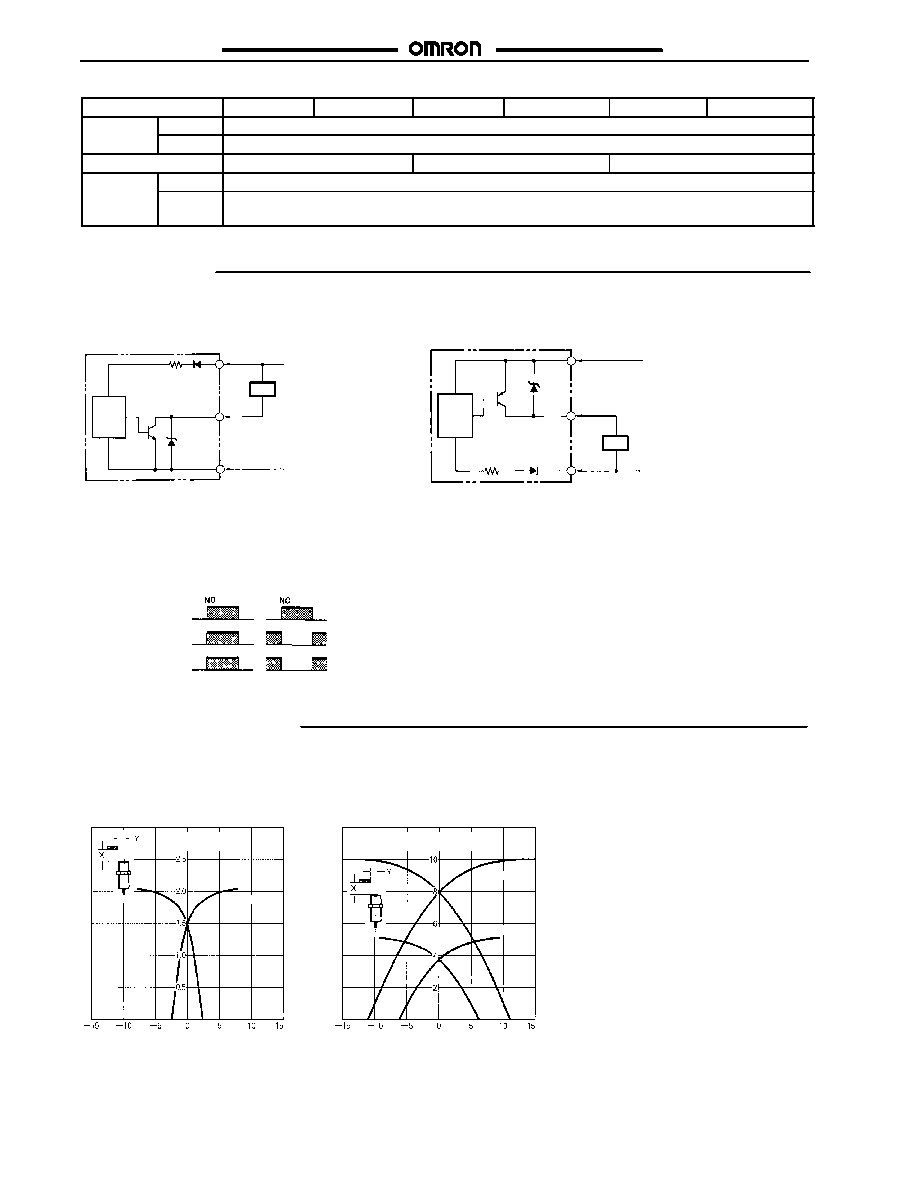
Control output
(switching capacity)
200 mA max., open collector
Circuit protection
Reverse connection protection, surge absorber, load short-circuit protection
Indicator
Operation indicator (red LED)
Ambient
temperature
Operating --40∞C to 85∞C (--40∞F to 185∞F) with no icing
Ambient
humidity
Operating 35% to 95%
Temperature influence
±15% max. of sensing distance at 23∞C in temperature range of --40∞C to 85∞C (--40∞F to 185∞F)
±10% max. of sensing distance at 23∞C in temperature range of --25∞C to 70∞C (--13∞F to 158∞F)
Voltage influence
±1% max. of sensing distance in rated voltage range ±15%
Residual voltage
2.0 V max. (under load current of 200 mA with cable length of 2 m)
Insulation resistance
50 M min. (at 500 VDC) between current carry parts and case
Dielectric strength
1,000 VAC for 1 min between current carry parts and case
Vibration resistance
10 to 55 Hz, 1.5-mm double amplitude for 10 times each in X, Y, and Z axes
Shock resistance
1,000 m/s
2
(approx. 100G) for 10 times each in X, Y, and Z axes
(This table continues on the next page.)