ICs for TV
1
AN5636K
SECAM/PAL signal conversion IC
s
Overview
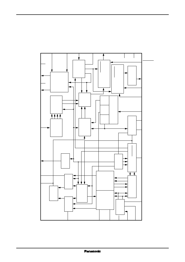
The AN5636K is an IC which converts the SECAM
signal into the quasi-PAL signal. This IC can add the
SECAM signal processing function while rationalizing
the external parts in a joint use with the PAL/NTSC sig-
nal processing IC: AN5606K.
s
Features
∑
Rationalizing IHDL in common use with PAL IHDL
∑
Lowering 6H line crawling by the quasi-PAL modula-
tion
∑
For both auto and manual modes of signal processing
s
Applications
∑
TV (applicable to three systems: PAL/NTSC/SECAM)
SDIP030-P-0400
Unit: mm
3
∞
to 15
∞
26.7
±
0.3
0.5
±
0.1
1.0
±
0.25
3.3
±
0.25
4.7
±
0.25
1
15
30
16
0.35
-
0.05
+
0.1
8.6
±
0.3
0.9
±
0.25
10.16
±
0.25
1.778

ICs for TV
AN5636K
3
Pin No.
Description
17
PAL color killer voltage input
18
Delay signal input
19
V
CC
(chroma system)
20
R
-
Y signal output
21
Reference bias power supply
22
B
-
Y signal output
23
System identification voltage output
combined with system forcing switch
24
4.43 MHz CW input
25
Line switch output
26
R
-
Y clamp capacitance
27
De-emphasis circuit
28
B
-
Y clamp capacitance
29
Discriminator
30
Discriminator
Pin No.
Description
1
GND (chroma-system)
2
SECAM chroma input
3
Limiter feedback
4
Limiter feedback
5
System discrimination holding capacitor
6
Identification pulse fall setting
7
Not SECAM video signal input
8
Sand castle pulse input
9
SECAM video signal input
10
GND (video system)
11
Video signal output
12
Not SECAM chroma signal input
13
V
CC
(video system)
14
PAL chroma signal output
15
Identification pulse rise setting
16
Direct signal input
s
Pin Descriptions
s
Absolute Maximum Ratings
Parameter
Symbol
Rating
Unit
Supply voltage
V
CC
6.0
V
Supply current
I
CC
100
mA
Power dissipation
*2
P
D
600
mW
Operating ambient temperature
*1
T
opr
-
20 to
+
70
∞
C
Storage temperature
*1
T
stg
-
55 to
+
150
∞
C
Note) *1 : Except for the operating ambient temperature and storage temperature, all ratings are for T
a
=
25
∞
C.
*2 : T
a
=
70
∞
C, Independent IC without a heat sink

ICs for TV
AN5636K
5
Parameter
Symbol
Conditions
Min
Typ
Max
Unit
1. DC
Circuit current
I
CC1
Pin 13: 5.0 V, pin 13: 5.0 V
40
58
76
mA
2. AC
Chroma block
SECAM input signal
V
30 (lim)
Pin 30 output, when pin 2 input is
-
1
0
+
1
dB
limiting range
4.328 MHz CW of 20 mV[p-p] to
400 mV[p-p]
Limiter amplifier gain
G
V30 (lim)
Pin 30 output, when pin 2 input is
18
28
38
dB
4.328 MHz CW of 2 mV[p-p]
SECAM demodulation
E
27 (B
-
Y)
Peak to peak voltage of D
B
at pin 27
159
227
295
mV[p-p]
output signal (B
-
Y)
for SECAM color bar chroma of
200 mV[p-p] input to pin 2
SECAM demodulation
E
27 (R
-
Y)
Peak to peak voltage of D
R
at pin 27
225
321
417
mV[p-p]
output signal (R
-
Y)
for SECAM color bar chroma of
200 mV[p-p] input to pin 2
SECAM demodulation
E
27 (R
-
Y/
Peak to peak voltage of D
R
vs. D
B
0.99
1.41
1.84
output ratio (R
-
Y/ B
-
Y)
B
-
Y)
at pin 27 for SECAM color bar
chroma of 200 mV[p-p] input to pin 2
SECAM modulation gain
G
S27-14
Peak to peak voltage of D
R
at pin 27
0.5
1.0
1.5
Times
vs. D
R
red at pin 14 for SECAM color
bar chroma of 200 mV[p-p] input to
pin 2
SECAM modulation
V
14 (R
-
Y/
At pin 14, D
R
red vs. D
R
burst for
2.34
3.35
4.36
output ratio (R
-
Y/ burst)
burst)
SECAM color bar chroma of
200 mV[p-p] input to pin 2
SECAM modulation
V
14 (R
-
Y/
At pin 14, D
R
red vs. D
R
blue for
0.99
1.41
1.84
output ratio (R
-
Y/ B
-
Y)
B
-
Y)
SECAM color bar chroma of
200 mV[p-p] input to pin 2
PAL chroma amp gain
G
P12-14
Pin 14 chroma output for PAL chroma
0.7
1.0
1.3
Times
330 mV[p-p] input to pin 12
Video block
Frequency characteristics
F
11SECAM
Pin 11 cutoff frequency for
10
MHz
(SECAM)
CW 0.3 V[p-p] input to pin 9
Frequency characteristics (PAL)
F
11PAL
Pin 11 cutoff frequency for
10
MHz
CW 0.3 V[p-p] input to pin 7
Gain (SECAM)
G
11SECAM
10 kHz CW output gain at pin 11 for
4
7
10
dB
10 kHz CW 0.3 V[p-p] input to pin 9
Gain (PAL)
G
11PAL
10 kHz CW output gain at pin 11 for
4
7
10
dB
10 kHz CW 0.3 V[p-p] input to pin 7
s
Electrical Characteristics at T
a
=
25
∞
C