 | –≠–ª–µ–∫—Ç—Ä–æ–Ω–Ω—ã–π –∫–æ–º–ø–æ–Ω–µ–Ω—Ç: AN618 | –°–∫–∞—á–∞—Ç—å:  PDF PDF  ZIP ZIP |
s Overview
The AN6182K and AN6182S are recording and playing
amplifier ICs for answering telephones. They incorporate an
ALC circuit, recording and playing amplifiers, a loudspeaker
amplifier, and a VOX circuit.
s Features
∑
Incorporates recording and playing amplifiers.
∑
Incorporates a loudspeaker amplifier.
∑
Incorporates a VOX circuit.
∑
Incorporates a magnetic-head circuit to provide for one-tape
cassette recording.
∑
Incorporates 4 control circuits.
AN6182K, AN6182S
Recording and playing amplifier IC
for answering telephones
6.2
±
0.3
21.7
±
0.3
4.7
±
0.25
3.05
±
0.25
1.1
±
0.25
1.778
0.5
±
0.1
0.9
±
0.25
7.62
±
0.25
3--15∞
0.30
+ 0.1
≠ 0.05
Unit : mm
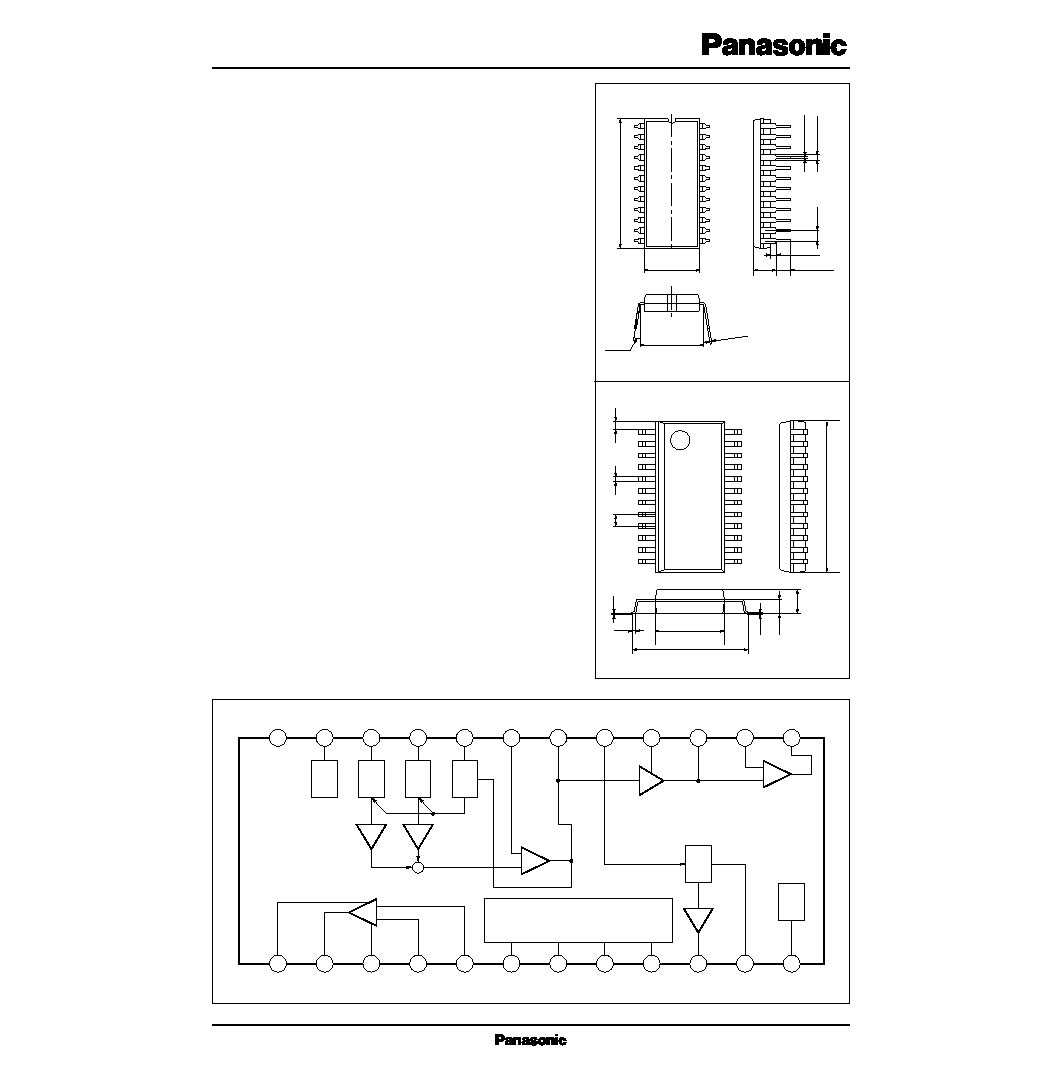
AN6182K
SDIP package with 24 pins (SDIP024-P-0300)
1
2
3
4
5
6
7
8
9
10
11
12
24
23
22
21
20
19
18
17
16
15
14
13
+
≠
24
23
22
21
20
19
18
17
16
15
14
13
1
2
3
4
5
6
7
8
9
10
11
12
MIC
LIN
+
≠
Com
PRE
Vcc
ALC
ALC
ALC
DET
+
VOX
DET
LOGIC
Pre Amp.
SPMUTE
PREMUTE
MIC
LIN
PLAY
REC
Vref
REG
REC
EQ
+
≠
SP
PRE GND
Power V
CC
Power GND
PRE V
CC
s Block Diagram
Unit : mm
0.45
0.6
±
0.3
0.3
2.0
±
0.2
0.925
0.15
1
9.4
±
0.3
7.2
±
0.3
15.3
±
0.3
AN6182S
SOP package with 24 pins (SOP024-P-0375)
1.27
12
13
24
0.1
±
0.1
2
3
4
5
6
7
8
9
10
11
23
22
21
20
19
18
17
16
15
14
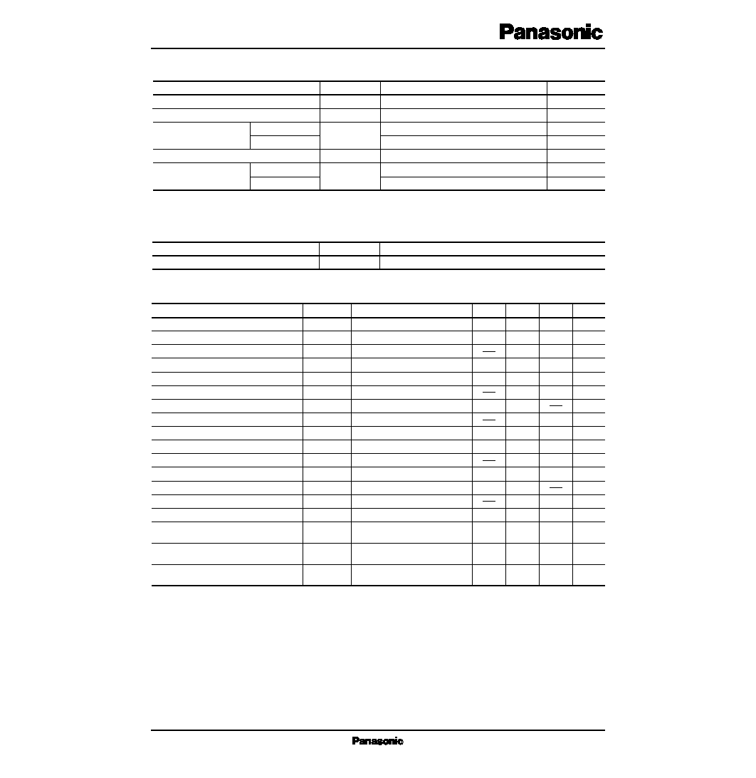
Supply voltage
Note 1)
Supply current
Note 1)
Power dissipation
Note 2)
Operating ambient temperature
Storage temperature
AN6182K
AN6182S
AN6182K
AN6182S
9.0
600
700
338
≠20 to + 75
≠55 to + 150
≠55 to + 125
V
mA
mW
mW
∞C
∞C
∞C
V
CC
I
CC
P
D
T
opr
T
stg
Parameter
Symbol
Rating
Unit
Note 1) The IC must be used under the condition V
CC
◊
I
CC
< P
D.
Note 2) Ta=60∞C
s Absolute Maximum Ratings (Ta=25∞C)
MIC preamp. gain
MIC preamp. ALC output
MIC preamp. output noise voltage
LIN preamp. gain
LIN preamp. ALC output
LIN preamp. output noise voltage
VOX sensitivity (1)
VOX sensitivity (2)
REC head drive
PRAY/EQ amp. gain
PRAY/EQ amp. output noise voltage
POWER amp. gain
POWER amp. max output voltage
POWER amp. output noise voltage
Pre. V
CC
voltage
PRE V
CC
voltage
Total circuit current (1)
Total circuit current (2)
G
V
V
O
V
no
G
V
V
O
V
no
V
S1
V
S2
G
V
G
V
V
no
G
V
V
O
V
no
V
CC
V
CC
I
total-1
I
total-2
Vi=≠64dBm
Vi=≠30dBm
DIN/AUDIO, Rg=10k
Vi=≠64dBm
Vi=≠30dBm
DIN/AUDIO, Rg=10k
Vi=≠35dBm
Vi=≠29dBm
Rg=1k
, Vi=≠10dBm
Vi=≠60dBm
DIN/AUDIO, Rg=10k
Vi=≠20dBm
R
L
=8
, THD=5%
DIN/AUDIO, Rg=10k
No signal, V
CC
=5V
No signal, V
CC
=5V
I
CC (Pre)
=0 to 6mA
No signal
recording mode (SP ON)
No signal
recording mode (SP OFF)
48.5
≠11
48.5
≠11
3.5
≠18.7
39.5
14.5
100
3.6
≠ 0.25
12
2
50.5
≠9
1.2
50.5
≠9
1.2
4.8
0.025
≠16.2
41.5
0.3
17
200
0.2
4.0
≠ 0.07
20
3.3
52.5
≠7
2.5
52.5
≠7
2.5
0.5
≠13.7
43.5
1.2
19.5
1.0
4.4
0.1
30
5
dB
dBm
mVrms
dB
dBm
mVrms
V
V
dBm
dB
mVrms
dB
mW
mVrms
V
V
mA
mA
Parameter
Symbol
Condition
min
typ
max
Unit
s Electrical Characteristics
Operating supply voltage range
4.5 to 9.6V
V
CC
Parameter
Symbol
Range
s Operating Supply Voltage Range

1
2
3
4
5
6
7
8
9
10
11
12
Pin No.
Symbol
Description
Power V
CC
Power out
Power GND
Power NF
Power in
SP mute control
Preamp.
mute control
MIC/LIN
control
REC/PLAY
control
VOX out
VOX DET
V
REF
s Pin Descriptions
13
14
15
16
17
18
19
20
EQ≠amp. out
EQ≠amp. NF
Head in/out
REC ADJ
VOX in
Pre out
Pre NF
ALC DET
Loudspeaker amplifier power supply input
An external power supply connects to this pin. The input supply voltage range is 4.5 to 9V.
Loudspeaker amplifier output
This pin connects through an electrolytic capacitor to a loudspeaker with a load impedance of 8
or
more. This pin is effective only when Pin6 is high.
Loudspeaker amplifier ground
This pin connects to an external ground. This ground should be separated from that of the preampli-
fier circuits.
Loudspeaker amplifier inverse input
A combination of resistors and a capacitor connected between this pin and Pin2 and the ground
determines the gain and frequency characteristics of the loudspeaker amplifier.
Loudspeaker amplifier non-inverse input
Signals should be input to this pin through a capacitor. The expected input impedance is typically 27k
.
Loudspeaker amplifier mute control
If the voltage level at this pin is high, the loudspeaker amplifier turns ON, and if low, turns OFF.
Preamplifier mute control
If the voltage level at this pin is high, the preamplifier turns OFF, thereby blocking the MIC and
line preamplifier outputs. If the voltage is low, the preamplifier turns ON. Even if the preamplifier
is turned OFF (mute ON), signals input to Pin9 are output from Pin18.
MIC/line preamplifier switching
If the input to Pin7 is low and the input to this pin is high, then the line preamplifier turns ON and
the MIC preamplifier turns OFF. If the input to Pin7 is low and the input to this pin is low, then the
line preamplifier turns OFF and the MIC preamplifier turns ON.
REC/PLAY switching
If the input to this pin is high, the recording amplifier turns OFF, and the play equalizer amplifier
turns ON. If low, the recording amplifier turns ON, and the play equalizer amplifier turns OFF.
VOX output
The VOX detection signal is output from this pin. This pin should be connected through a resistor
(100-200k
) to the power supply.
VOX detection control
This pin should be connected through a resistor (10 to 470k
) and a capacitor in parallel to the
ground. The resistance determines the sensitivity of VOX detection.
Internal reference supply voltage output
This pin should be grounded through a 100
µ
F capacitor.
Equalizer amplifier output
Amplified play signals from the head are output from this pin. A resistor and capacitors connected
between this pin and Pin14 determine the equalizer characteristics.
Equalizer amplifier inverse input
This pin connects through a resistor to Pin13 to determine the equalizer characteristics. The expect-
ed input impedance is typically 10k
.
To the REC/PLAY head
A REC/PLAY head must be connected between this pin and the ground. Switching of REC and
PLAY modes is done by Pin9. A load resistor should be connected between this pin and the ground
because the input impedance becomes high (several hundred kilohms) in the PLAY mode.
REC gain control
A resistance connected between this pin and the ground determines the head bias current in the REC
mode. The lower the resistance, the higher the current. A serial combination of a resistance and a
capacitance, connected in parallel with the resistance, determines the REC gain.
VOX amplifier input
The preamplifier output at Pin18 must be connected through a resistor and a capacitor to this pin.
The impedance between Pin18 and this pin determines the gain, and a resistance betweeen Pin11
and the ground determines the frequency characteristics of the VOX amplifier.
Preamplifier output
Amplified MIC/line preamplifier outputs are output from this pin depending on the the statuses of
Pin7 (preamplifier mute) and Pin8 (MIC/line switching).
Preamplifier inverse input
Resistors and a capacitor connected between this pin and Pin18 and 12 determine the preamplifier
gain. The input impedance at this pin is several hundred kilohms.
ALC detection control
A 240k
resistor and a 4.7
µ
F capacitor connected in parallel between this pin and the ground control ALC detection sensitivity.

21
22
23
24
LIN in
MIC in
PRE V
CC
PRE GND
Pin No.
Symbol
Description
s Pin Descriptions (cont.)
Line preamplifier input
Line receiver signals are input through a capacitor and a resistor to this pin, and then amplified to be
output from Pin18. The statuses of Pins7 and 8 enable or disable the signals. The input impedance
with ALC OFF is 10k
.
MIC preamplifier input
MIC signals are input through a capacitor and a resistor to this pin, and then amplified to be output
from Pin18. The statuses of Pins7 and 8 enable or disable the signals. The input impedance with
ALC OFF is 10k
.
Preamplifier internal regulated supply voltage output
This pin should be grounded through a 220
µ
F capacitor. The output voltage is typically 4.2V. The
output can be used as an ECM bias current source.
Preamplifier ground
This is the ground pin for the preamplifier circuits.
1
2
3
4
5
6
7
8
9
10
11
12
Loudspeaker amplifier power supply input
Loudspeaker amplifier output
Loudspeaker amplifier ground
Loudspeaker amplifier inverse input
Loudspeaker amplifier non-inverting input
Loudspeaker amplifier mute control
Preamplifier mute control
MIC/line preamplifier switching
REC/PLAY switching
VOX output
VOX detection control
Internal reference supply voltage output
Pin No.
Description
Pin No.
Description
13
14
15
16
17
18
19
20
21
22
23
24
Equalizer amplifier output
Equalizer amplifier inverting input
To the REC/PLAY head
REC gain control
VOX amplifier input
Preamplifier output
Preamplifier inverting input
ALC detection control
Line preamplifier input
MIC preamplifier input
Preamplifier internal regulated supply voltage output
Preamplifier ground
s Pin Descriptions

19
MICREC
18
16
15
13
22
21
5
4
Pre
REC
EQ
LINPRE
SP
2
6
7
8
9
6 SP MUTE
H
L
SP POWER
ON
OFF
9 PLAY/REC
H
L
REC
OFF
ON
EQ
ON
OFF
9 PRE AMP
H
L
L
iMIC/LIN
H
L
MIC PRE AMP
OFF
OFF
ON
LIN PRE AMP
OFF
ON
OFF
s Block Diagram Showing the Logic of Amplifies
1. Loudspeaker amplifier mute
2. REC/PLAY switching
3. Preamplifiers switching