 | –≠–ª–µ–∫—Ç—Ä–æ–Ω–Ω—ã–π –∫–æ–º–ø–æ–Ω–µ–Ω—Ç: AN6657 | –°–∫–∞—á–∞—Ç—å:  PDF PDF  ZIP ZIP |

ICs for Motor
s
Overview
The AN6657 and the AN6657S are the electronic gov-
ernors capable of controlling the forward/reverse speed,
fast forward, rewind, and start/stop of the micromotors
used for the radio/cassette tape recorders, automatic an-
swering telephone sets, and so on.
s
Features
∑
Wide operating supply voltage range ; V
CC
=4.5V to
14V
∑
Stable reference voltage (1.3V) and easy speed control
∑
Large starting torque and maximum control torque
∑
Good secular drift because of external power transistor
∑
Provided with the motor stop function ; I
CC
=20µA or
less at stop time
∑
Capable of controlling forward/reverse rotation, fast for-
ward/constant speed, and start/stop via 3 input pins
s
Applications
∑
Speed control of the micromotors for the radio cas-
settes
∑
Speed control of the micromotors for the microcas-
settes of the automatic answering telephone sets
∑
Control of the tape loading motors for the DATs, etc.
AN6657, AN6657S
Micromotor Forward/ Reverse Electronic Governors
1
2
3
4
5
6
7
8
21.7
±
0.3
1.2
±
0.25
3 ~ 15∞
Unit : mm
6.3
±
0.25
0.5
±
0.1
2.54
(3.45)
7.62
±
0.25
0.3
+ 0.1
≠ 0.05
0.51min.
3.8
±
0.25
16
15
14
13
12
11
10
9
AN6657
16-Lead DIP Package (DIP016-P-0300E)
16
15
14
13
12
11
10
9
1
2
3
4
5
6
7
8
Amp.
Drive Mode
Swiching Logic
Ref.Voltage
1k
10k
GND
V
CC
For./Rev.
Drive Circuit
s
Block Diagrom
Unit : mm
AN6657S
0.4
0.4
±
0.25
1.27
0.1
±
0.1
0.3
1.5
±
0.2
0.65
0.15
1
2
3
4
5
6
7
8
16
15
14
13
12
11
10
9
10.1
±
0.3
6.5
±
0.3
4.2
±
0.3
16-Lead SOP Package (SOP016-P-0300)

ICs for Motor
AN6657, AN6657S
s
Absolute Maximum Ratings
(Ta= 25∞C)
V
CC
I
CC
I
O
P
D
T
opr
T
stg
Supply Voltage
Supply Current
Output Current
Power Dissipation
Operating Ambient Temperature
Storage Temperature
V
mA
mA
mW
∞C
∞C
Parameter
Symbol
Rating
Unit
14.4
50
700
500
380
≠20 ~ + 70
≠55 ~ +150
≠55 ~ +125
AN6657
AN6657S
AN6657
AN6657S
s
Recommended Operating Range
(Ta = 25∞C)
Parameter
Symbol
Range
Operating Supply Voltage Range
V
CC
4.5V ~ 14V
s
Electrical Characteristics
(Ta = 25∞C)
V
CC
= 5V
V
CC
= 5V
V
CC
= 5V
Supply voltage at which a 50mA current flows to Ra
V
CC
= 4.5V, Ra
= 13
V
CC
= 5V, I
L
= 55mA, N
= 2000rpm
V
CC
= 5V, I
L
= 55mA, N
= 2000rpm
V
CC
= 5V, I
L
= 55mA, N
= 4000rpm
V
CC
= 4.5V ~ 9V, I
L
= 55mA
V
CC
= 4.5V, I
L
= 55mA ~ 90mA
V
CC
= 5V ~ 14V
V
CC
= 5V ~ 14V
V
CC
= 9V, R
T
= 1.3
V
CC
= 5V, Ta
= 0∞C ~ 60∞C
Parameter
Symbol
Condition
min.
typ.
max.
Unit
4
1.3
0
0
2
0.62
0.015
Bias Current
Prestart Current
Reference Voltage
Start Voltage
Start Current
Rated Load r.p.m
Forward/Reverse r.p.m Difference
FF/Rated r.p.m. Ratio
r.p.m. Characteristics on Voltage Change
r.p.m. Characteristics on Load Change
Switching Mode Input H
Switching Mode Input L
Current Limiting Starting Voltage
Ref. Voltage Temperature Characteristics
I
bias
I
stop
V
ref
V
CC (S)
I
ST
N
L
N
Logi
N
N
V
N
L
V
H
V
L
V
Lim
V
r
/Ta
mA
µ
A
V
V
mA
%
%
Times
rpm/V
rpm
V
V
V
%/∞C
1.1
130
≠10
≠5
1.85
3
0
0.55
10
20
1.5
3
10
5
2.15
50
120
6
0.7
0.7
≠
+
M
NC
4.3k
15k
1kB
680
2000
rpm/∞C
0.022
µ
F
0.01
µ
F
2SD2249
or
2SD2177
4.7
µ
F
3900
rpm/∞C
1.2
AN6657, AN6657S
+
≠
HKN≠3A6LDI (Ra=13
)
(National Micromotors Co., Ltd)
To Mechanism Controller, etc
V
CC
16
15
14
13
12
11
10
9
1
2
3
4
5
6
7
8
s
Application Circuit
ICs for Motor
AN6657, AN6657S
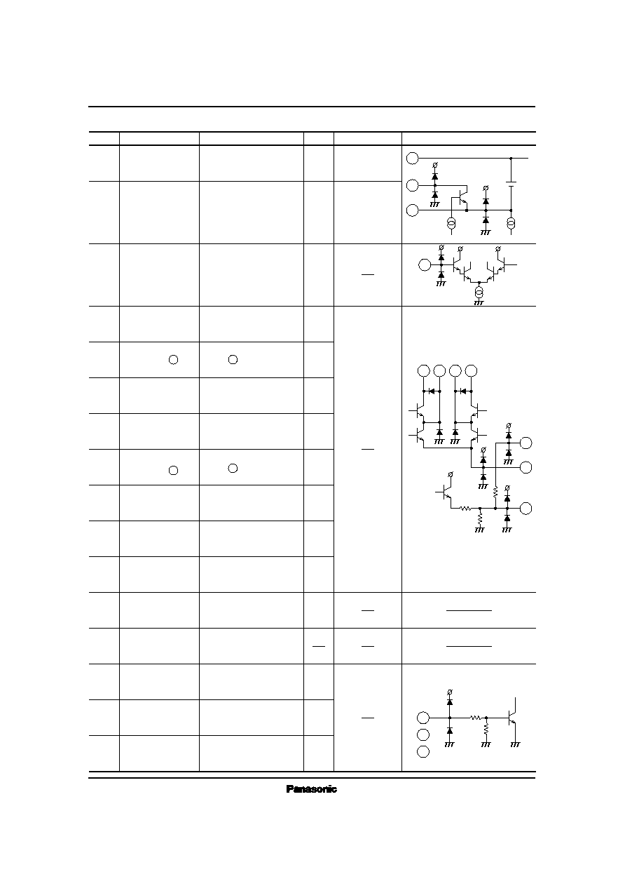
s
Pin Descriptions
Equivalent Circuit
Pin No.
Pin Name
Voltage
Description
I/O
1
Constant Speed
Setting
Constant speed setting pin
O
V
CC
≠ 1.3V
2
FF Setting
FF speed setting pin
O
V
CC
≠ 1.3V
3
Speed Control
Controls the speed
I
4
5
6
7
8
9
10
11
12
13
14
15
16
Phase Compensation
Motor Drive
Collector
Connection
Base Connection
Motor Drive
Load
Characteristics
Setting
V
CC
To the pin 9.
GND
NC
Start/Stop
Forward/Reverse
Constant Speed/FF
Oscillation preventive
phase compensation pin
Motor pin connection pin
Moror pin connection pin
V
CC
pin
Connect to the pin o.
GND pin
No connection
Forward/reverse control pin
Constant speed/FF control
pin
I
O
O
O
O
O
I
O
I
I
I
I
Collector connection pin of
the external NPN transistor
Base connection pin of the
external NPN transistor
Motor torque load
characteristics setting pin
Start/stop control pin
+
40k
30k
50
150
70k
V
REF
11
2
1
3
6
4
7
11
9
8
5
14
15
16
≠
+
≠

ICs for Motor
AN6657, AN6657S
s
Supplementary Explanation
∑ Principle of Functioning
The AN6657 and the AN6657S are the electronic
governors which control the motor speed constantly by
making use of the fact that the counter electromotive force
generated in the motor winding is proportional to the motor
speed when the DC motor rotates. They have two motor drive
systems which correspond to the forward and reverse
rotations, respectively. The inter-pin voltage of the motor Em
is given by the following expression.
Em = Ea + Ra Ia
Ea : Motor reverse electromotive voltage
Ra : Motor internal resistor
Ia : Motor current
There are the following relationships between the motor
reverse electromotive voltage Ea and Motor speed, and motor
torque T and motor current Ia, respectively.
Ea = Ka ∑ N
T = K
T
∑ Ia
Ka : Motor generation constant
K
T
: Motor torque constant
In the expression (1), the inter-pin voltage of the motor Em
includes the voltage Ra ∑ Ia which changes depending on
motor current Ia. The counter electromotive voltage Ea is
taken out by configuring the bridge circuit and used as a motor
speed signal. In Fig. 1, the motor speed N (
motor generated
voltage Ea) in the motor control state can be expressed by the
following formula.
+ V
CE SAT1
The expression (4) applies in case of motor forward rotation,
in which a current flows from the motor pin (5) to the
motor pin (8). The following expression applies in case of
motor reverse rotation, in which a current flows form the
motor pin (8) to the motor pin (5).
+V
CE SAT2
V
REF
: Reference voltage, Ra : Motor internal resistor
Ia : Motor current
r
2
, r
3
: Diffusion resistance in the IC, r
4
, r
5
: Resistance for
speed control
r
1
: Torque control Resistance
V
CE SAT1
: Forward/reverse drive circuit saturation voltage
when motor forward rotation is set
V
CE SAT2
: Forward/reverse drive circuit saturation voltage
when motor reverce rotation is set
(1)
Ea = V
REF
r
2
+ r
3
r
3
∑
r
4
+ r
5
r
5
+
r
1
r
2
r
3
≠ Ra Ia
(4)
≠
+
≠
(5)
Ea = V
REF
r
2
+ r
3
r
3
∑
r
4
+ r
5
r
5
+
r
1
r
2
r
3
≠ Ra Ia
Forward/
Reverse
Constant Speed/
Fast Forward
S/S
16
15
14
13
12
11
10
9
1
2
3
4
5
6
7
8
Amp.
0.022
µ
F
+
≠
M
NC
r
1
V
CC
Drive Mode
Switching Logic
Reference
Voltage
Forward/
Reverse
Drive Circuit
r
3
r
2
1k
10k
2SD2249
or
2SD2177
2SD2249
or
2SD2177
0.01
µ
F
r
6
4.3k
1kB
15k
680
Ra
Ea
4.7
µ
F
Ra : Motor-coiled resistor
Ea : Motor counter electromotive voltage
: Oscillation preventive capacitor
: Prevention of motor noise
1
10
Ra
<
1
2
2
1
=
+
≠
Fig.1 AN6657/AN6657S Motor Control Basic Circuit
r
4
r
5
(2)
(3)
+

ICs for Motor
AN6657, AN6657S
As it is clear from the expression (4), r
1
r
2
/r
3
≠ Ra = 0, that is,
when r
1
= r
3
/r
2
˜
Ra is established, Ea (
motor speed N)
becomes a constant value without depending on the motor
current Ia (load torque T). This is also true for the expression
(5).
∑ Switching the Various Modes
The AN6657 and the AN6657S have five motor drive
modes as shown in Table 1. Those modes can be selected
depending on the voltage H (3V to 6V) and voltage L (0V to
0.7V) signals applied to the input pins14, 15 and 16.
1) Forward/reverse switching : Forward/reverse rotation is
switched over whether a current flows from the pin5 to
the pin8 (forward rotation) or vice versa (reverse
rotation).
2) Power-off (pause) mode : turning off the constant current
source inside the IC stops a current to the motor and stops
motor. In this mode, all the transistors of the IC are turned
off and only a leak current (20
µ
A) is available.
3) Setting the motor speed
The motor speed at constant speed time can be expressed
by the expression (4).
In the FF (REW) mode, the pin2 is turned on and the first
term of the expression (4) is ;
+ V
CE SAT
and the motor speed N (motor generated voltage Ea) is
expressed as follows.
From the expression (4), the motor speed at constant speed
can be controlled with r
4
and r
5
(external VRs).
From the expression (6), the motor speed at the FF (REW)
mode can be controlled with r
6
.
<
The torque control resistance r
1
is important in setting the
motor rotating state. Select the resistance which satisfies the
condition of the expression (7) within a working temperature
range. If this condition is not satisfied, the motor may have
abnormal rotation such as hunting, etc.
Ra is the copper coiled resistor of the motor and has the
temperature characteristics of + 3,900r.p.m/∞C, Therefore, it
is necessary to set the value of r
1
so that the relationship in
the expression (7) will be satisfied at the minimum working
temperature. The diffusion resistance r
3
/r
2
in the IC has the
flat temperature characteristics, and if the temperature
characteristics of r
1
is adjusted to that of Ra, + 3900 r.p.m/∞C,
the value of the second term (r
1
r
2
r ≠ Ra) of the expressions
(4) and (5) shows the flat temperature characteristics and the
torque characteristics of the motor speed becomes constant
without depending on a temperature. Fig. 2 and Fig. 3 show
this relationship.
∑ Setting the External Resistor r
1
r
1
r
3
r
2
Ra
(r
3
/r
2
= 1/10 for the AN6657, AN6657S)
(7)
L
H
H
H
H
--
H
L
H
L
--
L
L
H
H
--
H
L
H
L
--
L
H
L
H
OFF
OFF
OFF
ON
ON
Pin14
Pin15
Pin16
Pin2
Pin5
Motor +
Pin8
Motor
≠
Input
Output
Motor Drive Mode
Power OFF (pause)
Forward (constant speed)
Reverse (constant speed)
FF
REW
Table 1 AN6657/AN6657S Mode Switching Table
V
REF
r
2
+r
3
r
3
∑
r
5
r
4
∑ r
6
r
4
+r
6
+ r
5
(6)
Ea =V
REF
∑
r
5
r
5
+
r
1
r
2
r
3
≠ Ra Ia
Low Temperature
Normal Temperature
High Temperature
T
M
(Torque)
Fig. 2 r
1
Temperature Characteristics < Ra Tempera-
ture Characteristics
N
(
R
.
P
.
M
.
)
r
2
+r
3
r
3
r
4
∑ r
6
r
4
+r
6
+