 | ÐлекÑÑоннÑй компоненÑ: AN7259S | СкаÑаÑÑ:  PDF PDF  ZIP ZIP |
Äîêóìåíòàöèÿ è îïèñàíèÿ www.docs.chipfind.ru
ICs for FM/AM Tuner
s
Overview
The AN7259S is an FMIF/DET IC for car radio/car
stereo and has each function necessary for electronic-
tuner.
s
Features
·
Quadrature detection system and fewer external parts
·
Good linearity of control voltage output used for AGC
and separation control, etc.
·
IF counter output and search output in channel selec-
tion signal as electronic tuning and with IF counter out-
put ON/OFF circuit (SSC)
·
Adjustment of search band width and search output
center frequency
·
Soft muting adjusting function
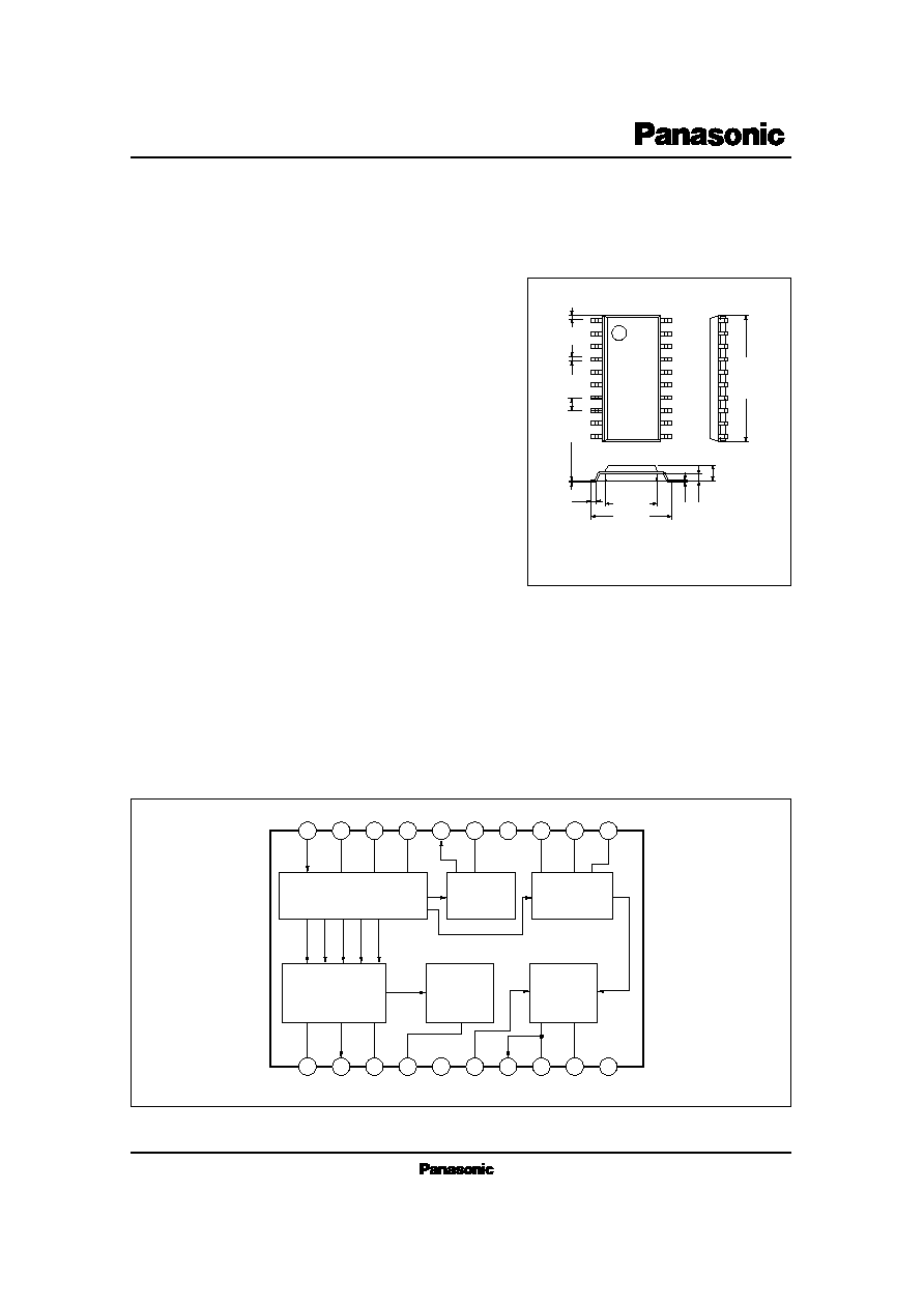
AN7259S
FM-IF Amplifier Circuit for Car Radio
20
19
18
17
16
15
14
13
12
11
1
2
3
4
5
6
7
8
9
10
FM IF Amp.
V
CONT.
Search
Counter
SSC
FM Det.
Mute
Amp.
GND
V
CC
s
Block Diagram
Unit : mm
0.1
±
0.1
1.5
±
0.2
0.3
0.65
0.15
0.4
1
2
3
4
5
6
7
8
9
10
20
19
18
17
16
15
14
13
12
11
0.4
±
0.25
1.27
12.6
±
0.3
5.4
±
0.3
7.7
±
0.3
20-Lead SOP Package (SOP020-P-0300A)
AN7259S
ICs for FM/AM Tuner
s
Absolute Maximum Ratings
(Ta=25°C)
V
CC
I
CC
P
D
T
opr
T
stg
Supply Voltage
Supply Current
Power Dissipation (Ta = 75°C)
Operating Ambient Temperature
Storage Temperature
V
mA
mW
°C
°C
Parameter
Symbol
Rating
Unit
9.6
23
230
30 ~ + 75
55 ~ + 125
AN7259S H2
s
Recommended Operating Range
(Ta=25°C)
Parameter
Symbol
Range
Operating Supply Voltage Range
V
CC
7.3V ~ 9.6V
Input at V
O
= 3dB
V
in
= 70dB
µ
V
in
= 0dB
µ
, Pin9 14
voltage
V
in
= 0dB
µ
, Pin2
voltage
V
SIG4
V
SIG1
V
SIG5
V
SIG4
V
in
= 70dB
µ
, Pin2
voltage
V
in
= 100dB
µ
, Pin2
voltage
Band width at Pin4
DC voltage
= 2.5V,
R
= 30k
V
in
= 0dB
µ
Mod.
= 30%, V
in
= 100dB
µ
Mod.
= 100%, V
in
= 100dB
µ
Mod.
= 30%, V
in
= 100dB
µ
Pin16, 10.7MHz Output
AM
= 30% Mod.,
FM
= 30% Mod.
V
in
= 0dB
µ
Referred to Input
Parameter
Symbol
Condition
min.
typ.
max.
Unit
s
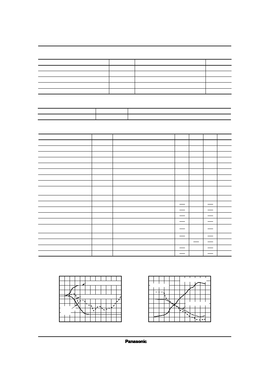
Electrical Characteristics
(V
CC
= 8V, FM 1kHz 30%Modulation, Ta= 25°C)
V
lim
V
O
V
offset
V
SIG1
V
SIG2
V
SIG3
V
SIG4
V
SIG5
BW
I
tot
26.5
150
240
0.19
2.51
1.15
2.92
4.11
145
15
30
32.5
210
240
0.85
3.33
1.75
3.98
5.56
185
23
dB
µ
mVrms
mV
V
V
V
V
V
kHz
mA
%
%
dB
mVrms
dB
dB
dB
V
Limiting Sensitivity
Detection Output Level
AFC Offset Voltage
Signal Voltage (1)
Signal Voltage (2)
Signal Voltage (3)
Signal Voltage (4)
Signal Voltage (5)
Search Signal Band Width
Supply Current
THD
THD
S/N
IF Counter Output Level
AMR
Residual Noise Level
Control Voltage Adjusting Width
Reference Voltage
AF Output Impedance
29.5
175
0
0.52
2.92
1.45
3.4
4.8
165
19
0.1
0.3
63
250
50
23
3.9
300
20
10
0
10
20
30
40
50
60
70
80
0
10 20
30 40 50
60 70
80 90 100 110 120
V
O
(
d
B
)
V
in
(dB
µ
)
Output Voltage, AMR V
in
5
4
3
2
1
0
0
10 20
30 40 50
60 70
80 90 100 110 120
V
c
o
n
t
(
d
B
)
V
in
(dB
µ
)
Control Voltage V
in
SD Output Pin4
FM 1kHz, 30% Modulation
AM 1kHz, 30% Modulation
Mute Voltage Pin3
Control Voltage Pin2
0% Modulation
(Noise)
s
Characteristics Curve
ICs for FM/AM Tuner
AN7259S
2.0
1.8
1.6
.
1.4
1.2
1.0
0.8
0.6
0.4
0.2
0
40
20
0
20
40
60
80
100
120
V
S
I
G
1
(
V
)
Ta (°C)
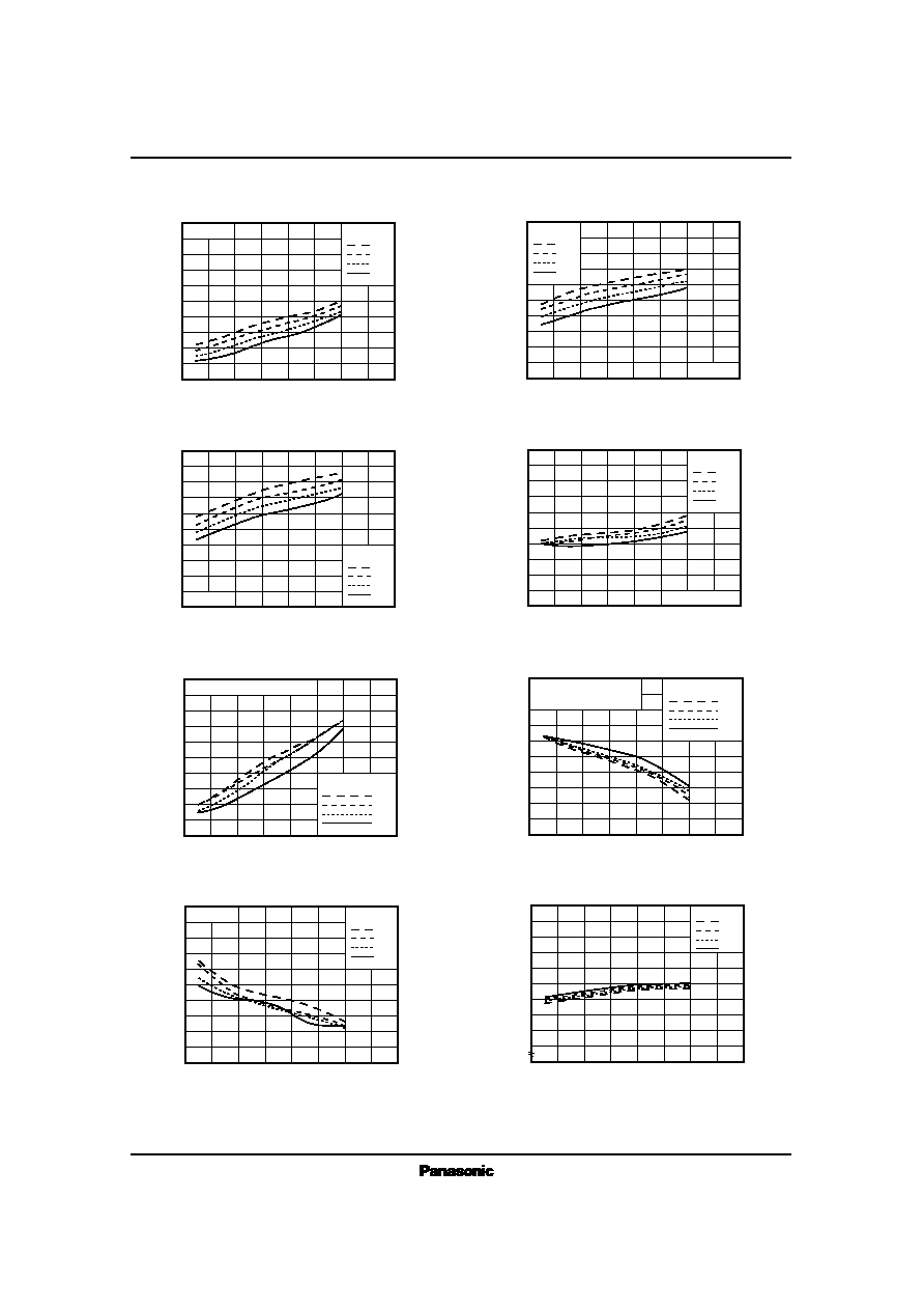
Signal Voltage (1) Ta
4.0
3.8
3.6
3.4
3.2
3.0
2.8
2.6
2.4
2.2
2.0
40
20
0
20
40
60
80
100
120
V
S
I
G
4
(
V
)
Ta (°C)
Signal Voltage (4) Ta
V
CC
10V
9V
8V
7V
5.0
4.8
4.6
4.4
4.2
4.0
3.8
3.6
3.4
3.2
3.0
40
20
0
20
40
60
80
100
120
V
S
I
G
5
(
V
)
Ta (°C)
Signal Voltage (5) Ta
V
CC
10V
9V
8V
7V
150
140
130
120
110
100
90
80
70
60
50
40
20
0
20
40
60
80
100
120
B
W
(
k
H
z
)
Ta (°C)
Search Band Width Ta
V
CC
10V
9V
8V
7V
35
34
33
32
31
30
29
28
27
26
25
40
20
0
20
40
60
80
100
120
V
l
i
m
(
d
B
µ
)
Ta (°C)
Limiting Sensitivity Ta
V
CC
10V
9V
8V
7V
200
190
180
170
160
150
140
130
120
110
100
40
20
0
20
40
60
80
100
120
V
o
(
m
V
)
Ta (°C)
Output Voltage Ta
V
CC
10V
9V
8V
7V
25
24
23
22
21
20
19
18
17
16
15
40
20
0
20
40
60
80
100
120
I
t
o
t
(
m
A
)
Ta (°C)
Supply Voltage I
tot
Ta
V
CC
10V
9V
8V
7V
4.1
4.0
3.9
3.8
3.7
40
20
0
20
40
60
80
100
120
V
r
e
f
(
V
)
Ta (°C)
Reference Voltage V
ref
Ta
V
CC
10V
9V
8V
7V
V
CC
10V
9V
8V
7V
V
in
= 0dB
µ
V
in
=100dB
µ
FM 1kHz 30% Modulation
V
in
= 0dB
µ
V
in
=70dB
µ
R
14 9
= 60k
FM 1kHz 30% Modulation
IF T Damp R=1k
AN7259S
ICs for FM/AM Tuner
20
19
18
17
16
15
14
13
12
11
1
2
3
4
5
6
7
8
9
10
AN7259S
+
+
+
+
330
0
.
0
2
2
µ
F
0
.
0
2
2
µ
F
0
.
2
2
µ
F
200k
2
0
0
k
IF COUNTER
OUT
REF
SSC
200k
820
15pF
1.2k
30kB
FROM
F.E.
0.22
µ
F
7.5k
1000pF
AF OUT
0.022
µ
F
V
CC
SEARCH
100k
0
.
0
2
2
µ
F
0
.
0
2
2
µ
F
2
2
k
10kB
2
.
2
µ
F
V
CONT.
OUT
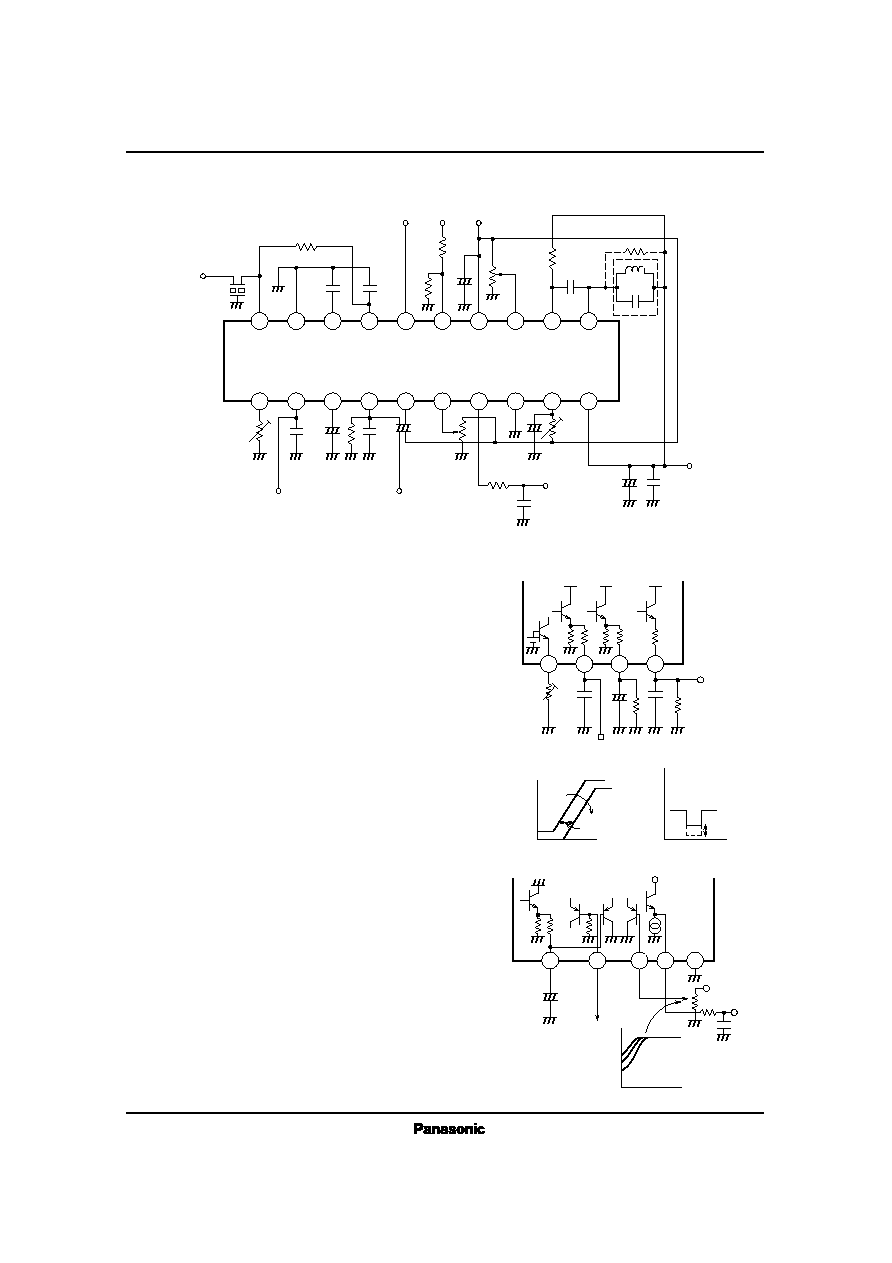
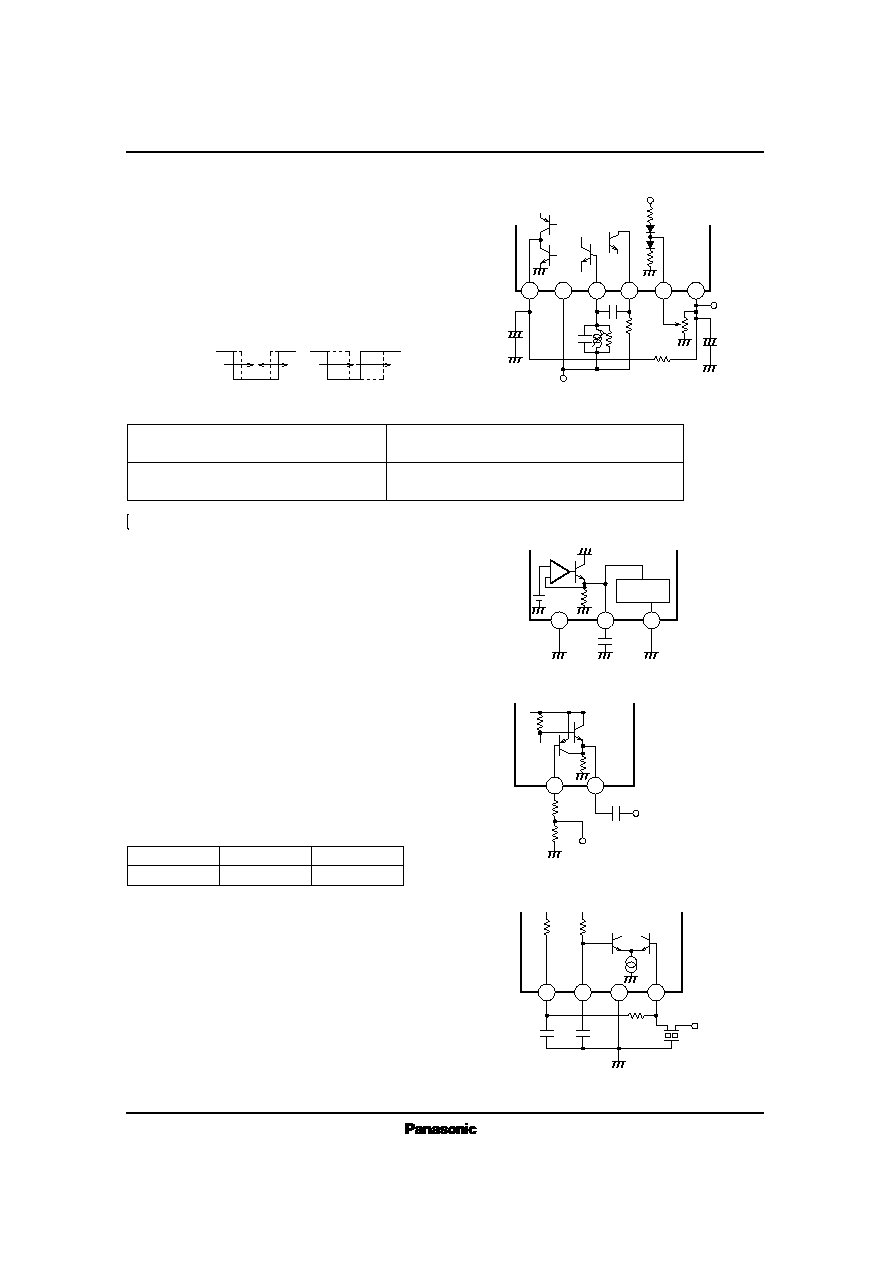
· Control Signal Output Block
The AN7259S has linear level meter output (control voltage on Pin2)
whose dynamic range is about 60dB wider for change of the input. This
control voltage is adjustable by the resistor R
4
of Pin1. The adjustable range
at R
4
= 0.8k
~ 10k
is more than 30dB in conversion of the input.
The polarity of the output voltage from Pin3 is reverse to that of the voltage
to be output from Pin2. This output from Pin3 requires insertion of a
capacitor (C
5
= 4.7
µ
F) since it is used for soft muting. The search output
(right sketch) to be used for channel selection is obtainable on Pin4. The
band width of this search output is adjustable. (Refer to Detection Block.)
The search stop sensitivity is externally adjustable because the L level
value varies with the input signal level.
· Soft Mute
Pin7 is the AF output pin, and the emitter follower output of
300
in
output impedance is obtainable on this pin.
Pin6 is the soft mute adjusting pin to adjust the attenuation at the non-input
mode.
Soft mute here denotes muting by the level signal output from Pin3, and
the soft mute response varies with the time constant of this voltage output.
The r
2
and C
12
are related to the weak input S/N and the soft mute ON time,
and with increase of the C
12
value, the weak input S/N is proportionately
improved, but the speed of response accordingly becomes lower. The r
1
, on
the other hand, is related to the soft mute OFF time. Each value specified in
the right sketch denotes a recommended value.
Control voltage output
1
2
3
4
10k
200
200
20k
Search output
R
6
C
6
C
5
C
4
R
5
R
4
0.22
µ
F
4.7
µ
F
1.8
k
0.022
µ
F
10kB
~ 20kB
Control voltage
Search output
Input
Increase of R
4
30dB
Frequency
3
5
6
7
8
V
REF
C
13
R
13
VR
AF
OUT
GND
To V
CC
C
12
+
4.7
µ
F
r
1
r
2
V
CC
200
36k
Soft mute
adj.
2k
s
Pin Descriptions
s
Application Circuit
ICs for FM/AM Tuner
AN7259S
· Detection Block
Pin11 and Pin12 constitutes a phase-shifting circuit of the QUAD detector
by external circuit.The R
7
is a coil damp resistor, and it exerts influences on
the noise, THD, and output level.
Its recommended value is 1.2k
~ 1.8k
.
Pin9 is the AFC voltage output pin,and according to the value of R
10
, the
band width of the Pin4 search output can be adjusted.
Pin13 is the center frequency adjusting pin of the Pin4 search output, and
makes it possible to adjust the center frequency of the search output
independently of the coil.
· Reference Voltage
(V
REF
)
The reference voltage (3.9V) is output from Pin14. Remember to bypass
it by an external capacitor since this line is used as the power supply line to
the limiter.
· IF Counter Output SSC
Pin16 is the IF counter output pin, and the output of about 300mV
P P
is
obtainable on this pin. Because of its high gain, the IF counter output line is
separated on the pattern from the Pin20 (IF input) line in order to avoid
oscillation trouble.
Pin15 is the SSC pin to stop the IF counter, and according to the
V
SSC
level, the IF counter operation changes as shown in the table be-
low. The H level must be 4.2V or higher, and the L level must be 1V
or lower. SSC is used for prevention of the bad influences of the IF
counter output on the other blocks in the receiving mode.
· IF Input Block
Pin20 is the IF input pin, and the input impedance is set between this pin
and Pin17 by R
1
. Usually a resistor of 330
is used as R
1
to secure
optimum matching with CF.
Pin17 and Pin18 are the internal DC feedback pins, and the high
frequency components are bypassed through C
1
and C
2
.
Pin19 is the GND pin dedicated to the limiter, and each GND of CF, C
2
and C
1
must be set close to Pin19. Externally short the GND of Pin19 with the GND
of Pin8.
30k
30k
CF
IF in
0.022
µ
F
C
2
C
1
0.022
µ
F
R
1
330
17
18
19
20
IF counter
V
SSC
ON
H
STOP
L
15
16
V
REF
20k
200k
200k
R
2
R
3
C
3
200pF
IF counter output
SSC IN (from microcomputer)
In case of channel selection by IF counter output
In case of channel selection by search output
Adjust the coil so that the V (9, 14) at V
in
= 0dB
µ
becomes
equal to V (9, 14) at V
in
= 100dB
µ
.
Same as above. Thereafter,adjust the center frequency of
the search output by the Pin13 VR.
V (9, 14) ··· DC voltage between Pin9 and Pin14
V
in
··· Level of IF input Pin20
*
An Example of Coil Adjusting Method
R
10
R
9
+
19
14
8
V
REF
Limiter
V
CC
10
13
14
V
CC
V
CC
43k
2
1
k
VR
200k
30k
15pF
820
R
8
C
11
R
7
1.2
k
C
8
C
9
C
7
0.2
µ
A
9
11
12
V
REF
R
10