CP800 THRU CP808
SINGLE-PHASE SILICON BRIDGE
VOLTAGE - 50 to 800 Volts CURRENT - P.C. MTG 3A, HEAT-SINK MTG 8A
Recongnized File #E111753
FEATURES
l
Surge overload rating--200 Amperes peak
l
Low forward voltage drop and reverse leakage
l
Small size, simple installation
l
Plastic package has Underwriter Laboratory
Flammability Classification 94V-O
l
Reliable low cost construction utilizing molded
plastic technique
MECHANICAL DATA
Mounting position: Any
Weight: 0.24 ounce, 6.9 grams
Terminals: Leads solderable per MIL-STD-202,
Method 208
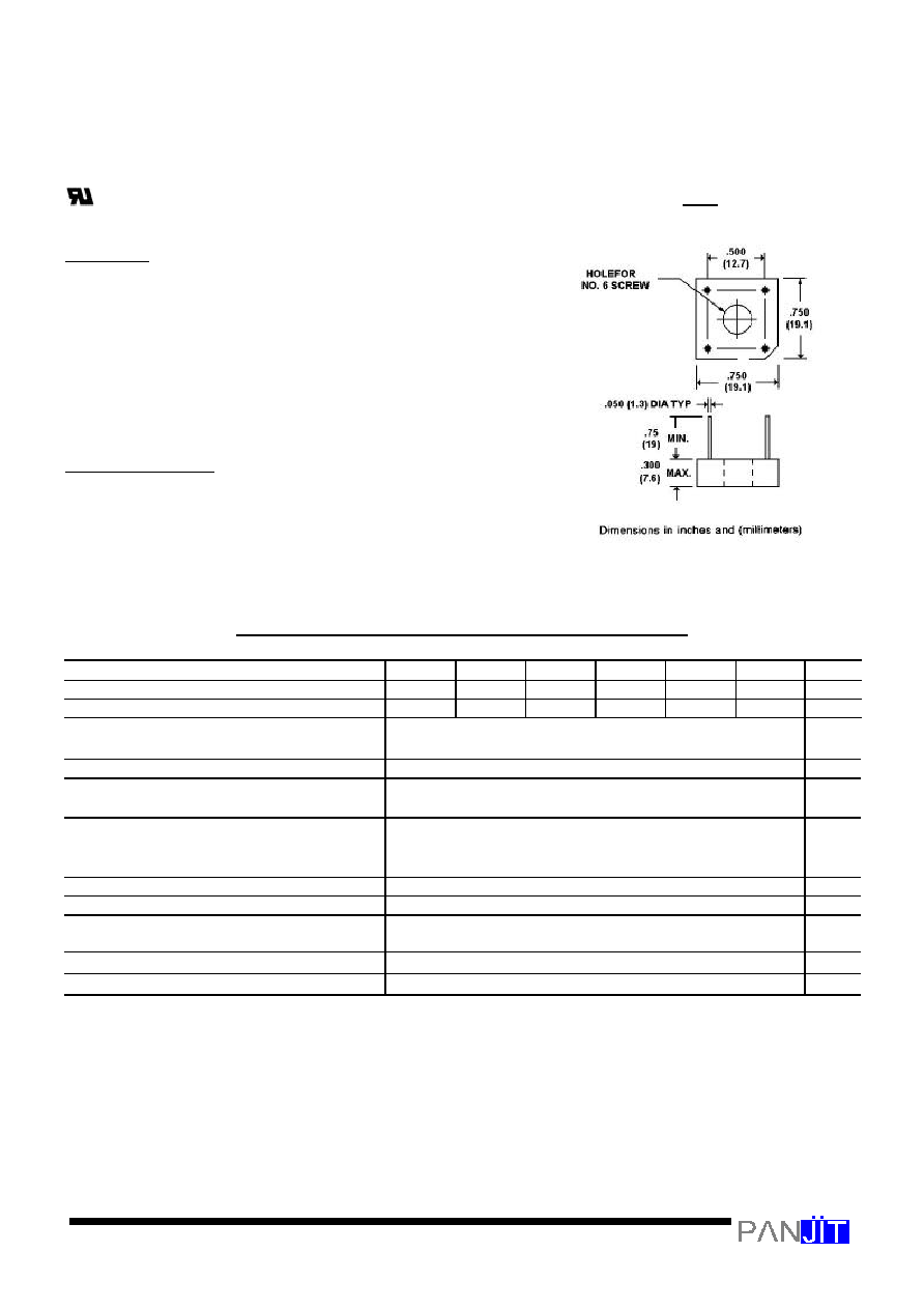
Mounting torque: Thro hole for #6 screw
MACXIMUM RATINGS AND ELECTRICAL CHARACTERISTICS
At 25
¢J
ambient temperature unless otherwise noted; resistive or inductive load at 60Hz .
CP800
CP801
CP802
CP804
CP806
CP808
UNITS
Max Recurrent Peak Reverse Voltage
50
100
200
400
600
800
V
Max Bridge Input Voltage RMS
35
70
140
280
420
560
V
Max Average Rectified Output at T
C
=50
¢J
*
See Fig. 2 at T
A
=40
¢J
**
8.0
3.0
A
A
Peak One Cycle Surge Overload Current
200
A
Max Forward Voltage Drop per element at
4.0A DC & 25
¢J
. See Fig. 3
1.1
V
Max Rev Leakage at rated Dc Blocking
Voltage per element at 25
¢J
See Fig 4 at100
¢J
10.0
1.0
£g
A
m
A
I
2
t Rating for fusing ( t<8.3ms)
166
A
2
Sec
Typical junction capacitance per leg (Note 4) CJ
200
P
F
Typical Thermal Resistance per leg (Note 3) R
£K
JA
Typical Thermal Resistance per leg (Note 2) R
£K
JL
21
6
¢J
/W
Operating Temperature Range
-55 TO +125
¢J
Storage Temperature Range
-55 TO +150
¢J
NOTES:
1. Bolt down on heat-sink with silicon thermal compound between bridge and mounting surface
for maximum heat transfer with #6 screw.
2. Units Mounted on a 8.6"
°—
8.6"
°—
24" thick (22
°—
22
°—
0.6cm) AL plate heatsink.
3. Units Mounted on P.C.B at 0.375"(9.5mm) lead length with 0.5
°—
0.5"(12
°—
12mm)copper pads.
4. Measured at 1.0MHZ and applied reverse voltage.
CP-8

RATING AND CHARACTERISTIC CURVES
CP800 THRU CP808
200
160
120
80
40
0
1
2 6
10
20 40 60 100
T
A
= 105
¢J
NO. OF CYCLES AT 60Hz
10
8
6
4
2
0
0
50
100 150
METAL HEATSINK
P.C. BOARD
(T
C
)
(T
A
)
AMBIENT TEMPERATURE,
¢J
Fig. 2-DERATING CURVE FOR OUTPUT RECTIFIED
CURRENT
5
4
3
2
1
.9
.8
.7
.5
.3
.2
.1
.07
.05
.03
.02
.01
0 0.2 0.4 0.6 0.8
1.0 1.2 1.4
TYPICAL
DISTRIBUTION
MEDIAN
INSTANTANEOUS FWD VOLTAGE, VOLTS
100
10
1
0
0
20 40
60 80
100 120 140
25
¢J
PERCENT OF RATED PEAK REVERSE VOLTAGE
Fig. 3-TYPICAL FORWARD CHARACTERISTICS(25
¢J
)
Fig. 4-REVERSE CHARACTERISTICS
O
U
T
P
U
T
C
U
R
R
E
N
T
A
M
P
E
R
E
S
F
O
R
W
A
R
D
S
U
R
G
E
C
U
R
R
E
N
T
,
A
M
P
E
R
E
S
p
k
(
H
A
L
F
S
I
N
E
W
A
V
E
)
I
N
S
T
A
N
T
A
N
E
O
U
S
R
E
V
E
R
S
E
C
U
R
R
E
N
T
,
£g
A
I
N
S
T
A
N
T
A
N
E
O
U
S
F
W
D
C
U
R
R
E
N
T
,
A
M
P
E
R
E
S