PAGE . 1
DATE : APR.18.2003
∑ Plastic material used carries Underwriters
Laboratory recognition 94V-O
∑ Low leakage
∑ Surge overload rating-- 50 amperes peak
∑ Ideal for printed circuit board
∑ Exceeds environmental standards of MIL-S-19500/228
MECHANICAL DATA
Case: Reliable low cost construction utilizing molded plastic technique
results in inexpensive product
Terminals: Lead solderable per MIL-STD-202, Method 208
Polarity: Polarity symbols molded or marking on body
Mounting Position: Any
Weight: 0.02 ounce, 0.4 gram
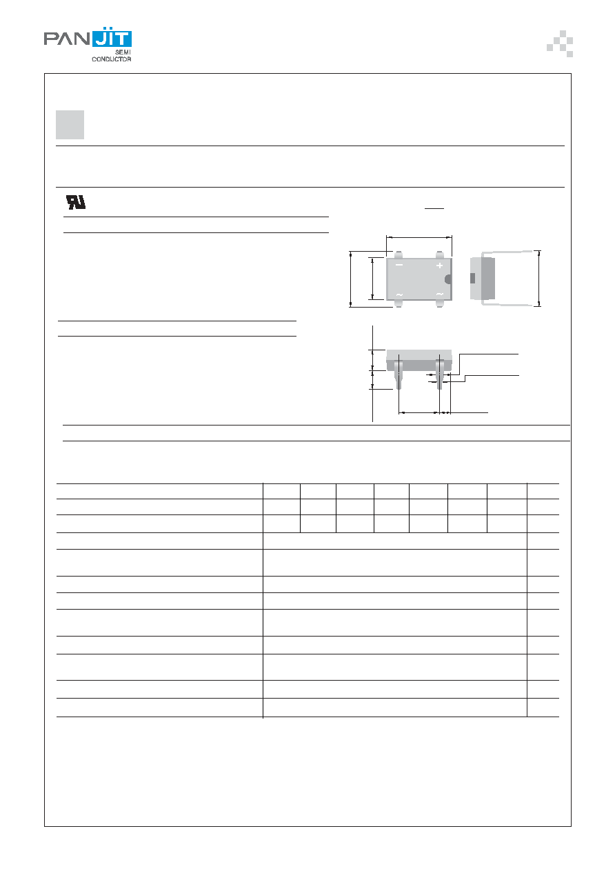
DI150~DI1510
DUAL-IN-LINE GLASS PASSIVATED SINGLE-PHASE BRIDGE RECTIFIER
VOLTAGE - 50 to 1000 Volts CURRENT - 1.5 Amperes
MAXIMUM RATINGS AND ELECTRICAL CHARACTERISTICS
Ratings at 25∞C ambient temperature unless otherwise specified.Single phase, half wave, 60Hz, Resistive or inductive load.
For capacitive load, derate current by 20%
Maximum Recurrent Peak Reverse Voltage
Maximum RMS Bridge input Voltage
Maximum DC Blocking Voltage
Maximum Average Forward Current T
A
=40∞C
Peak Forward Surge Current, 8.3ms singlehalf sine-wave
superimposed on rated load
I
2
t Rating for fusing ( t < 8.35 ms)
Maximum Forward Voltage Drop per Bridge Element at 1.0A
Maximum Reverse Current at Rated T
J
= 25∞C
DC Blocking Voltage per element T
J
=125∞C
Typical Junction capacitance per leg (Note 1) CJ
Typical Thermal resistance per leg (Note 2) R
JA
Typical Thermal resistance per leg (Note 2) R
JA
Operating Temperature Range T
J
Storage Temperature Range T
A
UNIT
NOTES:
1. Measured at 1.0 MHz and applied reverse voltage of 4.0 Volts
2. Thermal resistance from junction to ambient and from junction to lead mounted on P.C.B. with 0.5 X 0.5"(13 X 13mm) copper pads
DATA SHEET
DIP
Unit: inch ( mm )
.255
(6.5)
.245
(6.2)
.315
(8.00)
.285
(7.24)
.316 (8.05)
.335 (8.51)
.350(8.9)
.300(7.6)
.098(2.5)
.086(2.2)
.045 (1.14)
.035 (0.89)
.022 (0.56)
.018 (0.46)
.205 (5.2)
.195 (5.0)
.185
(4.69)
.150
(3.81)
.075 (1.90)
.055 (1.39)
1.5
A
50.0
A
10.0
V
A
2
t
1.1
5.0
0.5
25.0
40.0
15.0
-55 to 150
-55 to 125
µA
mA
∞C
∞C
∞C/W
pF
FEATURES
V
V
V
Recongnized File #E111753
DI150
50
35
50
DI151
100
70
100
DI152
200
140
200
DI154
400
280
400
DI156
600
420
600
DI158
800
560
800
DI1510
1000
700
1000
PAGE . 2
DATE : APR.18.2003
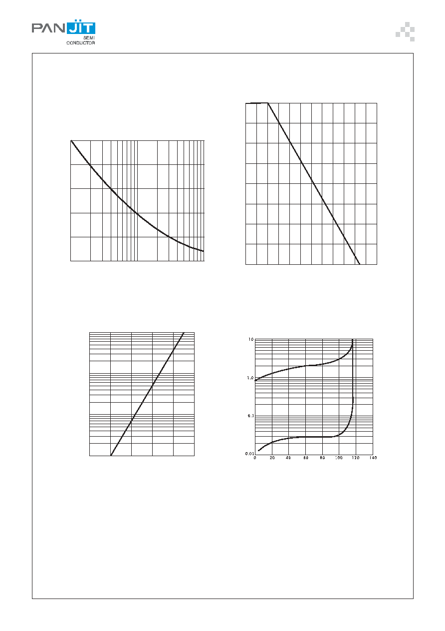
RATING AND CHARACTERISTIC CURVES
0.01
0.4
0.4
0.6
0.8
1.0
1.2
1.4
0.1
1.0
10.0
INSTANTANEOUS FORWARD VOLTAGE ,VOLTS
Fig. 3- TYPICAL
CHARACTERISTICS
FORWARD VOLTAGE
INST
ANT
A
NEOUS
F
ORW
ARD
CURRENT
,
AMPERES
INST
ANT
A
NEOUS
R
EVERSE
CURRENT
,
MICRO
AMPERES
PERCENT OF PEAK REVERSE VOLTAGE
Fig. 4- TYPICAL REAK REVERSE CHARACTERISTICS
NUMBER OF CYCLES AT 60HZ
Fig. 1- MAXIMUM NON-REPTITIVE
SURGE CURRENT
1
10
100
10
20
30
40
50
FORW
ARDSURGE
C
URRENT
,AMPERES
pk
(HALF
-SINE
W
A
V
E)
20
40
60
80
100
140
120
0
0.50
0.75
1.00
1.50
A
V
ERA
G
E
F
ORW
ARD
OUTPUT
CURRENT
,
A
MPERES
AMBIENT TEMPERATURE, C
O
Fig. 2- DERATING CURVE FOR OUTPUT RECTIFIED CURRENT