PAGE . 1
Approve Sheet
Part Number: KBU4A~KBU4K
FEATURES
∑ Plastic material has Underwriters Laboratory
Flammability Classification 94V-O
∑ Ideal for printed circuit board
∑ Reliable low cost construction utilizing molded plastic technique
∑ Surge overload rating: 150 Amperes peak
∑ High temperature soldering guaranteed:
260∞C/10 seconds/.375"(9.5mm) lead length at 5 lbs. (2.3kg) tension
KBU4A~KBU4K
SILICON SINGLE-PHASE BRIDGE RECTIFIER
VOLTAGE - 50 to 800 Volts CURRENT - 4.0 Amperes
Recongnized File # E111753
MECHANICAL DATA
Case: Reliable low cost construction utilizing
molded plastic technique
Terminals: Leads solderable per MIL-STD-202,
Method 208
Mounting position: Any
Mounting torque: 5 in. lb. Max.
Weight: 0.3 ounce, 8.0 grams
MAXIMUM RATINGS AND ELECTRICAL CHARACTERISTICS
Rating at 25∞Cambient temperature unless otherwise specified. Resistive or inductive load, 60Hz.
For Capacitive load derate current by 20%.
DATA SHEET
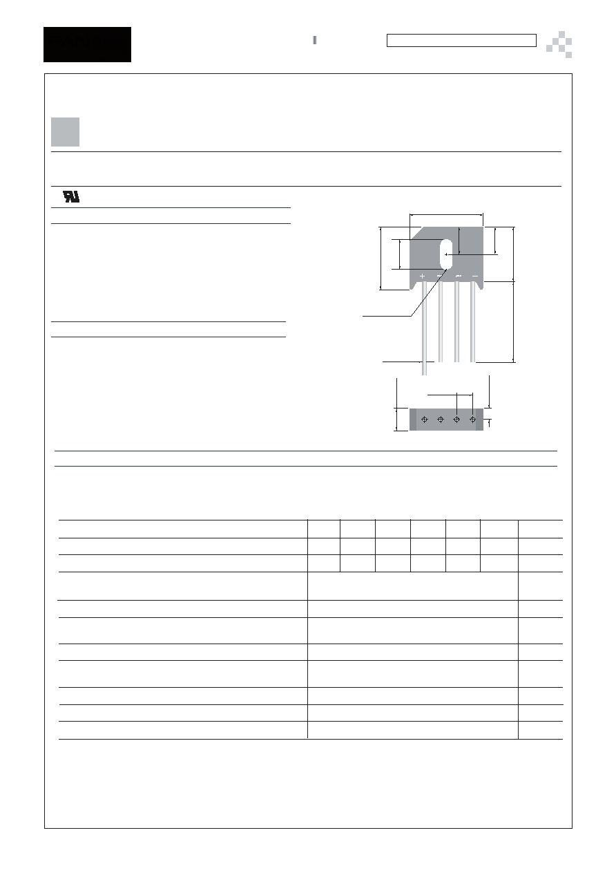
KBU
Unit: inch ( mm )
.224
(5.7
)
.295 (7.5
)
1.0(25.4)
MIN.
R .075(1.9) (2x)
.052(1.3)
.047(1.2)
.280
(7.1
)
.268
(6.8
)
.138
(3.5
)
.220(5.6)
.181(4.6)
.780
(19.8
)
.740
(18.8
)
.701
(17.8
)
.661
(16.8
)
.933(23.7)
.894(22.7)
~
~
Maximum Recurrent Peak Reverse Voltage
Maximum RMS Input Voltage
Maximum DC Blocking Voltage
Maximum Average Forward T
C
=100∞C
Rectified Output Current atT
A
=40∞C
I
2
t Rating for fusing ( t<8.3ms)
Peak Forward Surge Current single sine-wave superimposed on rated load
(JEDEC method)
Maximum Instantaneous Forward Voltage Drop per element at 4.0A
Maximum Reverse Leakage at rated T
A
=25∞
CDc Blocking Voltage per element T
C
=100∞C
Typical Thermal Resistance per leg(Note 2) R
JA
Typical Thermal Resistance per leg(Note 3) R
JC
Operating and Storage Temperature Range, T
J
,TSTG
V
V
V
A
A
2
sec
Apk
µA
∞C / W
UNIT
∞C
NOTES:
1. Recommended mounting position is to bolt down on heatsink with silicone thermal compound for maximum heat transfer with #6 screw.
2. Units Mounted in free air, no heatsink, P.C.B at 0.375"(9.5mm) lead length with 0.5 x 0.5"(12 x 12mm)copper pads.
3. Units Mounted on a 2.0 x 1.6" x 0.3" thick (5 x 4 x 0.8cm) AL plate.
µA
50
35
50
Vpk
4.0
4.0
93
150
1.0
10
1000
19
4
-55 to +150
∞C / W
KBU4A
100
70
100
KBU4B
200
140
200
KBU4D
400
280
400
KBU4G
600
420
600
KBU4J
800
560
800
KBU4K
PAGE . 2
Approve Sheet
Part Number: KBU4A~KBU4K
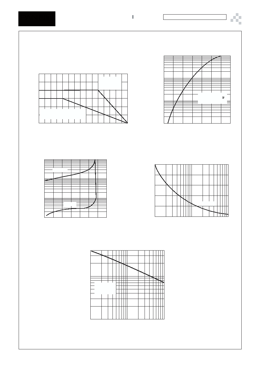
A
V
ERA
G
E
F
ORW
ARD
CURRENT
AMPERES
MOUNTED ON PC BOARD.
TA 0.5"(12.7mm) LEAD LENGTH
60Hz RESISTIVE OR INDUCTIVE LOAD
TEMPERATURE C
O
Fig. 1- DERATING CURVE FOR OUTPUT RECTIFIED CURRENT
RATING AND CHARACTERISTIC CURVES
HEAT-SINK
MOUNTING,TC
(4* 4* 0.15) INCH
COPPER PLATE
INSTANTANEOUS FORWARD VOLTAGE, VOLTS
Fig. 2- TYPICAL INSTANTANEOUS FORWARD
CHARACTERISITCS PER ELEMENT
INST
ANT
A
NEOUS
F
ORW
ARD
CURRENT
,
A
MPERES
TJ=25OC
Pulse Width=300 S
1% DULY Cycle
INST
ANT
A
NEOUS
R
EVERSE
CURRENT
,
MICRO
AMPERES
PERCENT OF PEAK REVERSE VOLTAGE
Fig. 3- TYPICAL REAK REVERSE CHARACTERISTICS
T =100 C
C
O
T =25 C
A
O
FPRW
ARD
SURGE
C
URRENT
,
A
MPERES
pk
(HALF
SINE-
W
A
V
E)
NO. OF CYCLES AT 62Hz
Fig. 4- MAXIMUM NON-REPETITEVE PEAK
FORWARD SURGE CURRENT
T =105 C
A
O
CAP
A
CIT
ANCE,
p
F
REVERSE VOLTAGE, VOLTS
Fig. 5- TYPICL JUNCTION CAPACITANCE PER ELEMENT
Tj=25 C
f=1.0MHz
Vsig=50mVp-p
O
6.0
4.0
2.0
0
0
50
100
150
100
40
20
10
4.0
2.0
1.0
0.4
0.2
0.1
0.7
0.8
0.9
1.0
1.1
1.2
1.3
1.4
10
1.0
0.1
0.01
0
20
40
60
80
100
120
140
150
120
90
60
30
0
1
2
6
10
20
40
60
100
400
100
50
10
1
5
10
50
100