
1.
General description
The 74AHC2G/AHCT2G32 is a high-speed Si-gate CMOS device. This device provides
two 2-input OR gates.
2.
Features
s
Symmetrical output impedance
s
High noise immunity
s
ESD protection:
x
HBM EIA/JESD22-A114-A exceeds 2000 V
x
MM EIA/JESD22-A115-A exceeds 200 V
x
CDM EIA/JESD22-C101 exceeds 1000 V.
s
Low power dissipation
s
Balanced propagation delays
s
SOT505-2 and SOT765-1 package
s
Specified from
-
40
∞
C to +85
∞
C and
-
40
∞
C to +125
∞
C.
3.
Quick reference data
[1]
C
PD
is used to determine the dynamic power dissipation (P
D
in
µ
W).
P
D
= C
PD
◊
V
CC
2
◊
f
i
◊
N +
(C
L
◊
V
CC
2
◊
f
o
) where:
f
i
= input frequency in MHz;
f
o
= output frequency in MHz;
74AHC2G32; 74AHCT2G32
Dual 2-input OR gate
Rev. 01 -- 23 February 2004
Product data sheet
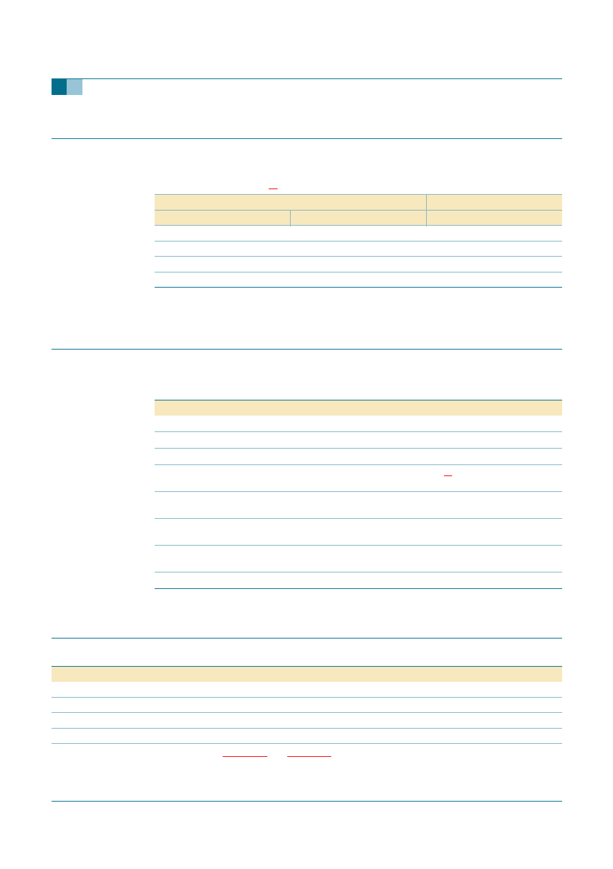
Table 1:
Quick reference data
GND = 0 V; T
amb
= 25
∞
C; t
r
= t
f
3.0 ns.
Symbol
Parameter
Conditions
Min
Typ
Max
Unit
Type 74AHC2G
t
PHL
, t
PLH
propagation delay
nA and nB to nY
C
L
= 15 pF;
V
CC
= 5 V
-
3.2
5.5
ns
C
I
input capacitance
-
1.5
10
pF
C
PD
power dissipation
capacitance
C
L
= 50 pF;
f
i
= 1 MHz
[1] [2]
-
16
-
pF
Type 74AHCT2G
t
PHL
, t
PLH
propagation delay
nA and nB to nY
C
L
= 15 pF;
V
CC
= 5 V
-
3.3
6.9
ns
C
I
input capacitance
-
1.5
10
pF
C
PD
power dissipation
capacitance
C
L
= 50 pF;
f
i
= 1 MHz
[1] [2]
-
17
-
pF

9397 750 12532
© Koninklijke Philips Electronics N.V. 2004. All rights reserved.
Product data sheet
Rev. 01 -- 23 February 2004
2 of 16
Philips Semiconductors
74AHC2G32; 74AHCT2G32
Dual 2-input OR gate
C
L
= output load capacitance in pF;
V
CC
= supply voltage in Volts;
N = total load switching outputs;
(C
L
◊
V
CC
2
◊
f
o
) = sum of the outputs.
[2]
The condition is V
I
= GND to V
CC
.
4.
Ordering information
5.
Marking
6.
Functional diagram
Table 2:
Ordering information
Type number
Package
Temperature range
Name
Description
Version
74AHC2G32DP
-
40
∞
C to +125
∞
C
TSSOP8
plastic thin shrink small outline package; 8 leads;
body width 3 mm; lead length 0.5 mm
SOT505-2
74AHCT2G32DP
-
40
∞
C to +125
∞
C
TSSOP8
plastic thin shrink small outline package; 8 leads;
body width 3 mm; lead length 0.5 mm
SOT505-2
74AHC2G32DC
-
40
∞
C to +125
∞
C
VSSOP8
plastic very shrink small outline package; 8 leads;
body width 2.3 mm
SOT765-1
74AHCT2G32DC
-
40
∞
C to +125
∞
C
VSSOP8
plastic very shrink small outline package; 8 leads;
body width 2.3 mm
SOT765-1
Table 3:
Marking
Type number
Marking code
74AHC2G32DP
A32
74AHCT2G32DP
C32
74AHC2G32DC
A32
74AHCT2G32DC
C32
Fig 1.
Functional diagram.
Fig 2.
IEC logic symbol.
mna733
1A
1B
1Y
2
1
7
2A
2B
2Y
6
5
3
mna734
7
1
1
2
1
3
6
5

9397 750 12532
© Koninklijke Philips Electronics N.V. 2004. All rights reserved.
Product data sheet
Rev. 01 -- 23 February 2004
3 of 16
Philips Semiconductors
74AHC2G32; 74AHCT2G32
Dual 2-input OR gate
7.
Pinning information
7.1 Pinning
7.2 Pin description
Fig 3.
Logic diagram (logic driver).
mna166
B
A
Y
Fig 4.
Pin configuration.
32
1A
V
CC
1B
1Y
2Y
2B
GND
2A
mna732
1
2
3
4
6
5
8
7
Table 4:
Pin description
Pin
Symbol
Description
1
1A
data input
2
1B
data input
3
2Y
data output
4
GND
ground (0 V)
5
2A
data input
6
2B
data input
7
1Y
data output
8
V
CC
supply voltage
9397 750 12532
© Koninklijke Philips Electronics N.V. 2004. All rights reserved.
Product data sheet
Rev. 01 -- 23 February 2004
4 of 16
Philips Semiconductors
74AHC2G32; 74AHCT2G32
Dual 2-input OR gate
8.
Functional description
8.1 Function table
[1]
H = HIGH voltage level;
L = LOW voltage level.
9.
Limiting values
[1]
The input and output voltage ratings may be exceeded if the input and output current ratings are observed.
10. Recommended operating conditions
Table 5:
Function table
[1]
Input
Output
nA
nB
nY
L
L
L
L
H
H
H
L
H
H
H
H
Table 6:
Limiting values
In accordance with the Absolute Maximum Rating System (IEC 60134). Voltages are referenced to
GND (ground = 0 V).
Symbol
Parameter
Conditions
Min
Max
Unit
V
CC
supply voltage
-
0.5
+7.0
V
V
I
input voltage
-
0.5
+7.0
V
I
IK
input diode current V
I
<
-
0.5 V
-
-
20
mA
I
OK
output diode
current
V
O
<
-
0.5 V or V
O
> V
CC
+ 0.5 V
[1]
-
±
20
mA
I
O
output source or
sink current
V
O
>
-
0.5 V or V
O
< V
CC
+ 0.5 V
-
±
25
mA
I
CC
, I
GND
V
CC
or GND
current
-
±
75
mA
T
stg
storage
temperature
-
65
+150
∞
C
P
tot
power dissipation
T
amb
= -
40
∞
C to +125
∞
C
-
250
mW
Table 7:
Recommended operating operations
Symbol
Parameter
Conditions
Min
Typ
Max
Unit
Type 74AHC2G
V
CC
supply voltage
2.0
5.0
5.5
V
V
I
input voltage
0
-
5.5
V
V
O
output voltage
0
-
V
CC
V
T
amb
operating ambient
temperature
see
Section 11
and
Section 12
per device
-
40
+25
+125
∞
C

9397 750 12532
© Koninklijke Philips Electronics N.V. 2004. All rights reserved.
Product data sheet
Rev. 01 -- 23 February 2004
5 of 16
Philips Semiconductors
74AHC2G32; 74AHCT2G32
Dual 2-input OR gate
11. Static characteristics
t
r
, t
f
input rise and fall
times
V
CC
= 3.3 V
±
0.3 V
-
-
100
ns/V
V
CC
= 5 V
±
0.5 V
-
-
20
ns/V
Type 74AHCT2G
V
CC
supply voltage
4.5
5.0
5.5
V
V
I
input voltage
0
-
5.5
V
V
O
output voltage
0
-
V
CC
V
T
amb
operating ambient
temperature
see
Section 11
and
Section 12
per device
-
40
+25
+125
∞
C
t
r
, t
f
input rise and fall
times
V
CC
= 5 V
±
0.5 V
-
-
20
ns/V
Table 7:
Recommended operating operations
...continued
Symbol
Parameter
Conditions
Min
Typ
Max
Unit
Table 8:
Static characteristics type 74AHC2G32
At recommended operating conditions; voltages are referenced to GND (ground = 0 V).
Symbol
Parameter
Conditions
Min
Typ
Max
Unit
T
amb
= 25
∞
C
V
IH
HIGH-level input
voltage
V
CC
= 2.0 V
1.5
-
-
V
V
CC
= 3.0 V
2.1
-
-
V
V
CC
= 5.5 V
3.85
-
-
V
V
IL
LOW-level input
voltage
V
CC
= 2.0 V
-
-
0.5
V
V
CC
= 3.0 V
-
-
0.9
V
V
CC
= 5.5 V
-
-
1.65
V
V
OH
HIGH-level output
voltage
V
I
= V
IH
or V
IL
I
O
=
-
50
µ
A; V
CC
= 2.0 V
1.9
2.0
-
V
I
O
=
-
50
µ
A; V
CC
= 3.0 V
2.9
3.0
-
V
I
O
=
-
50
µ
A; V
CC
= 4.5 V
4.4
4.5
-
V
I
O
=
-
4.0 mA; V
CC
= 3.0 V
2.58
-
-
V
I
O
=
-
8.0 mA; V
CC
= 4.5 V
3.94
-
-
V
V
OL
LOW-level output
voltage
V
I
= V
IH
or V
IL
I
O
= 50
µ
A; V
CC
= 2.0 V
-
0
0.1
V
I
O
= 50
µ
A; V
CC
= 3.0 V
-
0
0.1
V
I
O
= 50
µ
A; V
CC
= 4.5 V
-
0
0.1
V
I
O
= 4.0 mA; V
CC
= 3.0 V
-
-
0.36
V
I
O
= 8.0 mA; V
CC
= 4.5 V
-
-
0.36
V
I
LI
input leakage current
V
I
= V
CC
or GND; V
CC
= 5.5 V
-
-
0.1
µ
A
I
CC
quiescent supply
current
V
I
= V
CC
or GND; I
O
= 0 A;
V
CC
= 5.5 V
-
-
1.0
µ
A
C
I
input capacitance
-
1.5
10
pF