 | –≠–ª–µ–∫—Ç—Ä–æ–Ω–Ω—ã–π –∫–æ–º–ø–æ–Ω–µ–Ω—Ç: BLU11SL | –°–∫–∞—á–∞—Ç—å:  PDF PDF  ZIP ZIP |
Document Outline
- DESCRIPTION
- FEATURES
- QUICK REFERENCE DATA
- PIN CONFIGURATION
- PINNING - SOT122D.
- RATINGS
- THERMAL RESISTANCE
- CHARACTERISTICS
- APPLICATION INFORMATION
- RUGGEDNESS
- PACKAGE OUTLINE
- DEFINITIONS
- LIFE SUPPORT APPLICATIONS

DATA SHEET
Product specification
July 1986
DISCRETE SEMICONDUCTORS
BLU11/SL
UHF power transistor
July 1986
2
Philips Semiconductors
Product specification
UHF power transistor
BLU11/SL
DESCRIPTION
N-P-N silicon planar epitaxial
transistor primarily intended for use in
mobile transmitters in the 470 MHz
band.
FEATURES
∑
multi-base structure and
emitter-ballasting resistors for an
optimum temperature profile.
∑
gold metallization ensures
excellent reliability.
∑
the device can be applied at a P
L
of
max. 1,5 W when it is mounted on a
printed wiring board (see Fig.6)
without an external heatsink.
The transistor has a 4-lead envelope
with a ceramic cap (SOT-122D). All
leads are isolated from the mounting
base.
QUICK REFERENCE DATA
R.F. performance in a common-emitter class-B circuit.
Note
1. Device mounted on a printed wiring board (see Fig.6).
MODE OF OPERATION
T
∞
C
V
CE
V
f
MHz
P
L
W
G
p
dB
C
%
narrow band; c.w.
T
mb
= 25
12,5
470
2,5
>
10
>
55
T
a
= 25
(1)
12,5
470
1,5
>
12
>
55
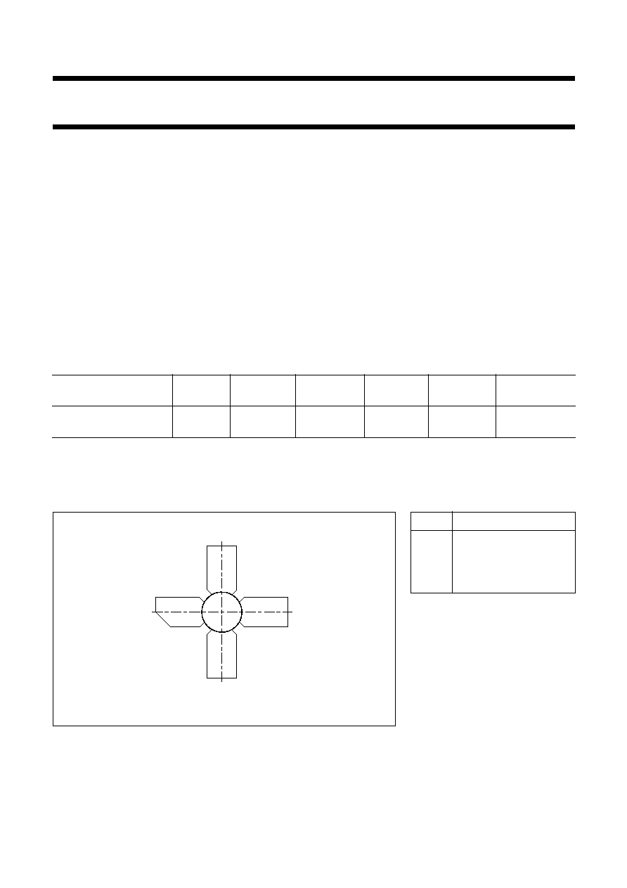
PIN CONFIGURATION
Fig.1 Simplified outline. SOT122D.
handbook, halfpage
2
3
1
4
MSB055
PINNING - SOT122D.
PIN
DESCRIPTION
1
collector
2
emitter
3
base
4
emitter
PRODUCT SAFETY This device incorporates beryllium oxide, the dust of which is toxic. The device is entirely
safe provided that the BeO disc is not damaged.
July 1986
3
Philips Semiconductors
Product specification
UHF power transistor
BLU11/SL
RATINGS
Limiting values in accordance with the Absolute Maximum System (IEC 134)
THERMAL RESISTANCE
Dissipation = 4,5 W
Note
1. Device mounted on a printed wiring board (see Fig.6).
Collector-base voltage (open emitter)
V
CBO
max.
36 V
Collector-emitter voltage (open base)
V
CEO
max.
16 V
Emitter-base voltage (open collector)
V
EBO
max.
3 V
Collector current
d.c. or average
I
C
; I
C(AV)
max.
0,4 A
(peak value), f
>
1 MHz
I
CM
max.
1,2 A
Total power dissipation
at T
mb
90
∞
C; f
>
1 MHz
P
tot(rf)
max.
6 W
Storage temperature
T
stg
-
65 to
+
150
∞
C
Operating junction temperature
T
j
max.
200
∞
C
From junction to ambient
(1)
at T
a
= 25
∞
C; f
>
1 MHz (r.f. operation)
R
th j-a (rf)
max.
50 K/W
From junction to mounting base
at T
mb
= 25
∞
C; f
>
1 MHz (r.f. operation)
R
th j-mb (rf)
max.
15 K/W
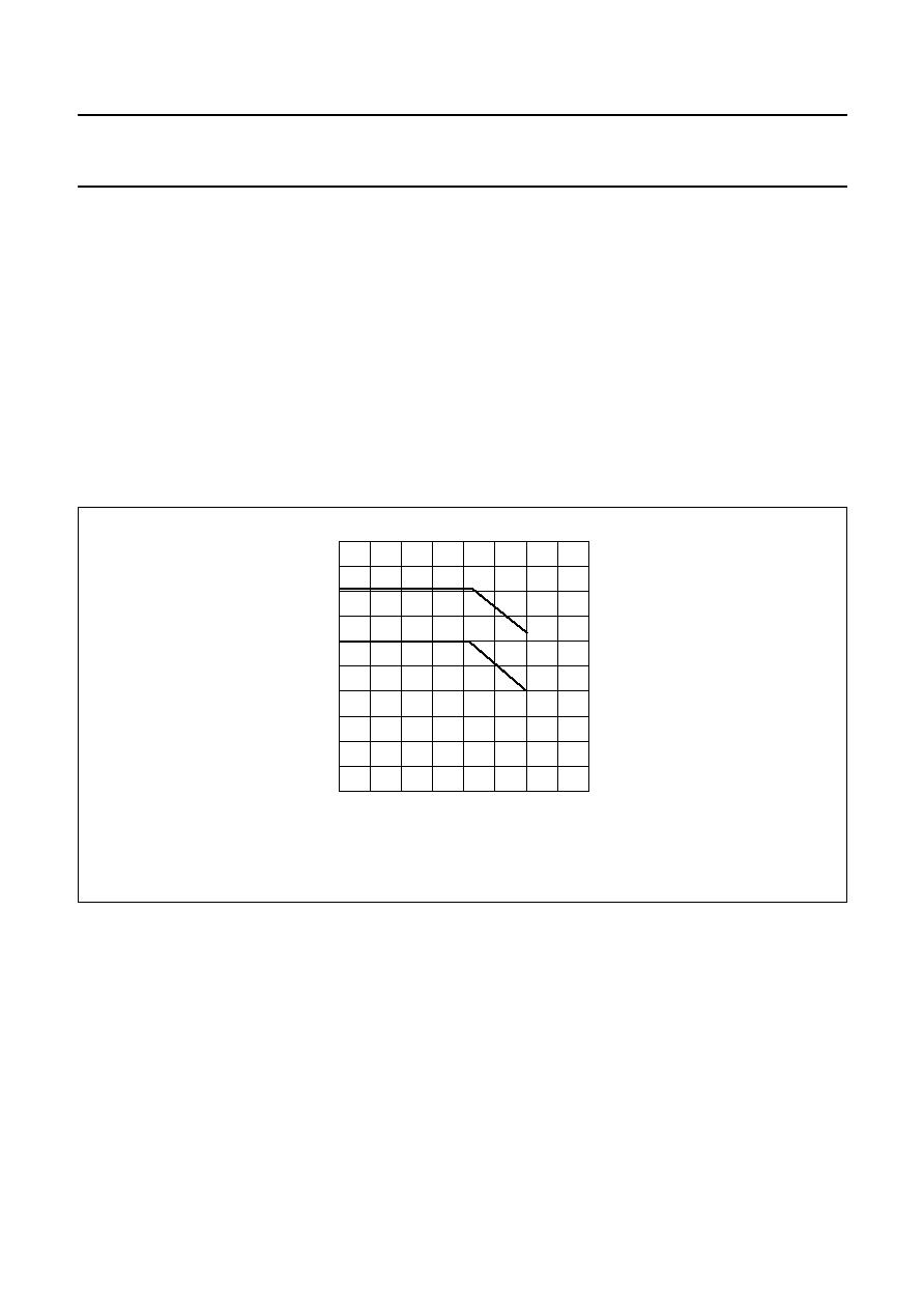
Fig.2 Power/temperature derating curves.
I Continuous r.f. operation (f
>
1 MHz)
II Short-time r.f. operation during mismatch (f
>
1 MHz)
handbook, halfpage
0
II
I
40
80
Ptot(rf)
(W)
Tmb (
∞
C)
160
10
0
8
120
6
4
2
MDA306

July 1986
4
Philips Semiconductors
Product specification
UHF power transistor
BLU11/SL
CHARACTERISTICS
T
j
= 25
∞
C unless otherwise specified
Collector-base breakdown voltage
open emitter; I
C
= 5 mA
V
(BR)CBO
min.
36 V
Collector-emitter breakdown voltage
open base; I
C
= 10 mA
V
(BR)CEO
min.
16 V
Emitter-base breakdown voltage
open collector; I
E
= 0,5 mA
V
(BR)EBO
min.
3 V
Collector cut-off current
V
BE
= 0; V
CE
= 16 V
I
CES
max.
2,5 mA
Second breakdown energy
L = 25 mH; f = 50 Hz; R
BE
= 10
E
SBR
min.
0,55 mJ
D.C. current gain
I
C
= 0,3 A; V
CE
= 10 V
h
FE
min.
25
Collector capacitance at f = 1 MHz
I
E
= i
e
= 0; V
CB
= 12,5 V
C
c
typ.
4 pF
Feedback capacitance at f = 1 MHz
I
C
= 0; V
CE
= 12,5 V
C
re
typ.
2,5 pF
Collector-mounting base capacitance
C
c-mb
typ.
1,2 pF
Fig.3 T
j
= 25
∞
C; typical values.
handbook, halfpage
0
VCE =
12.5 V
10 V
120
80
40
0
400
hFE
IC (mA)
800
1200
MDA307
Fig.4 I
E
= i
e
= 0; f = 1 MHz; typical values.
handbook, halfpage
0
20
10
0
2
4
6
8
4
8
12
Cc
(pF)
VCB (V)
16
MDA308

July 1986
5
Philips Semiconductors
Product specification
UHF power transistor
BLU11/SL
APPLICATION INFORMATION
R.F. performance in common-emitter circuit; class-B; f = 470 MHz; circuit tuned at P
L
= 2,5 W.
List of components:
Notes
1. American Technical Ceramics capacitor type B or capacitor of the same quality.
2. Device mounted on a printed wiring board (see Fig.6).
MODE OF OPERATION
T
∞
C
V
CE
V
f
MHz
P
L
W
G
p
dB
C
%
narrow band; c.w.
T
mb
= 25
12,5
470
2,5
>
10
>
55
T
mb
= 25
typ. 12
typ. 60
T
a
= 25
(2)
12,5
470
1,5
>
12
>
55
C1 = C2 = 2-9 pF film dielectric trimmer (cat. no. 2222 809 09002)
C3 = 1,6 pF multilayer ceramic chip capacitor
(1)
C4 = 10 pF multilayer ceramic chip capacitor
(1)
C5 = 100 pF multilayer ceramic chip capacitor
C6 = 3
◊
100 nF multilayer ceramic chip capacitor (cat. no. 2222 809 47104)
C7 = 2,2
µ
F (35 V) tantalum electrolytic capacitor
C8 = 1,4 - 55 pF film dielectric trimmer (cat. no. 2222 809 09001)
C9 = 5,6 pF multilayer ceramic chip capacitor
(1)
L1 = 56
stripline (25,5 mm
◊
2 mm)
L2 = L3 = 25
stripline (11 mm
◊
6 mm)
L4 = 132 nH; 6 turns closely wound enamelled Cu-wire (1 mm), int. dia. 6 mm, leads 2
◊
5 mm
L5 = Ferroxcube h.f. choke, grade 3B (cat. no. 4312 020 36642)
L6 = 16 nH; 1 turn enamelled Cu-wire (1 mm), int. dia. 6 mm, leads 2
◊
5 mm
R1 = 10
; ±
5% 0,4 W metal film resistor
R2 = 10
; ±
5% 0,4 W metal film resistor
L1, L4 and L5 are striplines on a double Cu-clad printed wiring board with PTFE fibre-glass dielectric (
r
= 2,2) and a
thickness
1
/
32
inch; thickness of copper-sheet 2
◊
35
µ
m.
handbook, full pagewidth
MDA309
,,,,,,
,,,,,,
,,,
,,,
T.U.T.
C2
C3 R1
C4
C5
C6
C7
L5
R2
L1
C1
L3
L4
L2
L6
C9
C8
50
50
+VCC
Fig.5 Class-B test circuit at f = 470 MHz.