 | ÐлекÑÑоннÑй компоненÑ: BLV20 | СкаÑаÑÑ:  PDF PDF  ZIP ZIP |
Äîêóìåíòàöèÿ è îïèñàíèÿ www.docs.chipfind.ru

DATA SHEET
Product specification
August 1986
DISCRETE SEMICONDUCTORS
BLV20
VHF power transistor
August 1986
2
Philips Semiconductors
Product specification
VHF power transistor
BLV20
DESCRIPTION
N-P-N silicon planar epitaxial
transistor intended for use in class-A,
B and C operated h.f. and v.h.f.
transmitters with a nominal supply
voltage of 28 V. The transistor is
resistance stabilized and is
guaranteed to withstand severe load
mismatch conditions.
It has a 3/8" flange envelope with a
ceramic cap. All leads are isolated
from the flange.
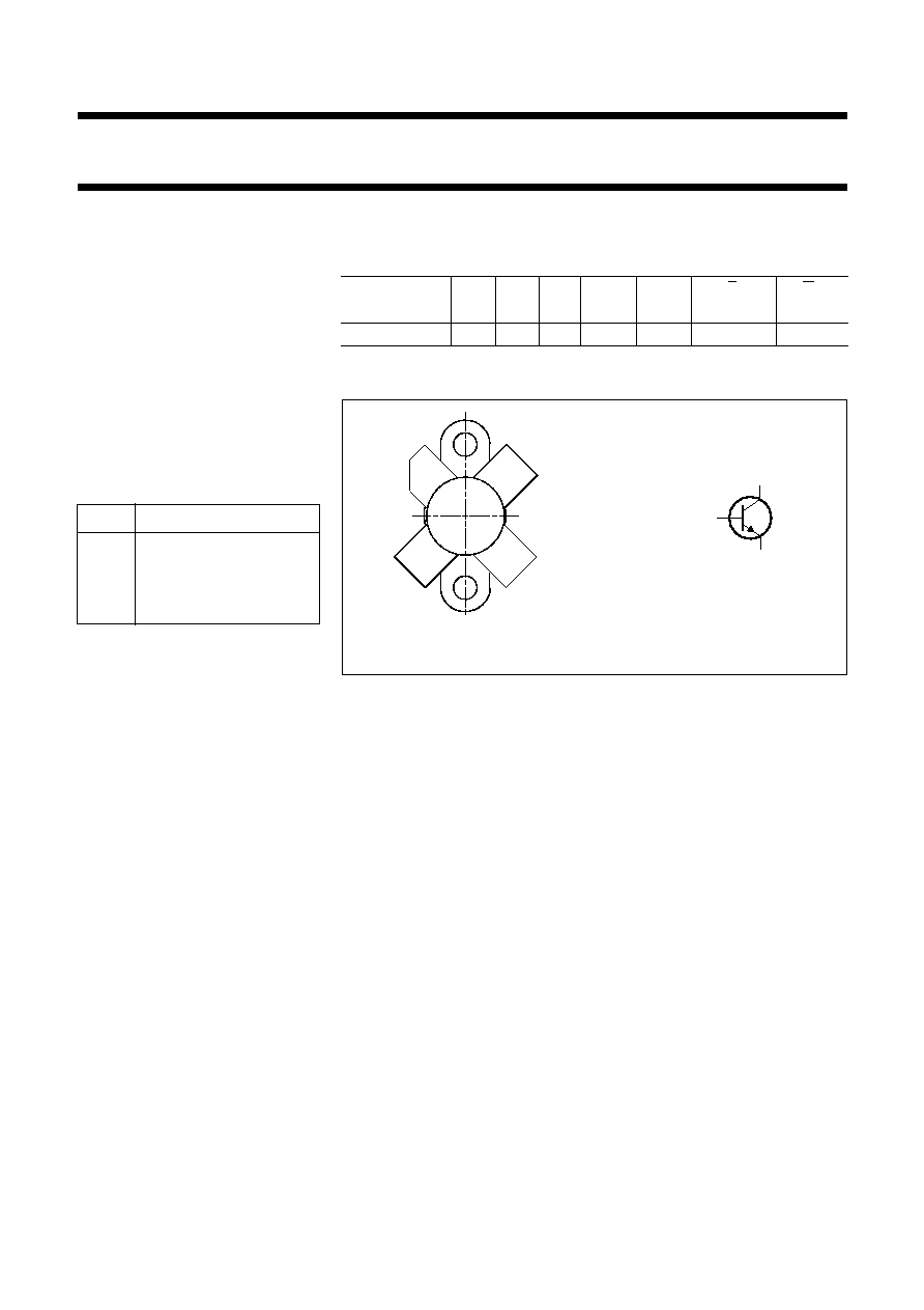
PINNING - SOT123
PIN
DESCRIPTION
1
collector
2
emitter
3
base
4
emitter
QUICK REFERENCE DATA
R.F. performance up to T
h
= 25
°
C in an unneutralized common-emitter
class-B circuit
PIN CONFIGURATION
PRODUCT SAFETY This device incorporates beryllium oxide, the dust of
which is toxic. The device is entirely safe provided that the BeO disc is
not damaged.
MODE OF
OPERATION
V
CE
V
f
MHz
P
L
W
G
p
dB
%
z
i
Y
L
mS
c.w.
28
175
8
>
12
>
65
1,8
+
j0,7
18
-
j20
handbook, halfpage
e
c
b
MBB012
Fig.1 Simplified outline and symbol.
halfpage
1
2
3
4
MSB057
August 1986
3
Philips Semiconductors
Product specification
VHF power transistor
BLV20
RATINGS
Limiting values in accordance with the Absolute Maximum System (IEC 134)
Collector-emitter voltage (V
BE
= 0)
peak value
v
CESM
max.
65 V
Collector-emitter voltage (open base)
V
CEO
max.
36 V
Emitter-base voltage (open collector)
V
EBO
max.
4 V
Collector current (average)
I
C(AV)
max.
0,9 A
Collector current (peak value); f
>
1 MHz
I
CM
max.
2,5 A
R.F. power dissipation (f
>
1 MHz); T
mb
= 25
°
C
P
rf
max.
20 W
Storage temperature
T
stg
-
65 to
+
150
°
C
Operating junction temperature
T
j
max.
200
°
C
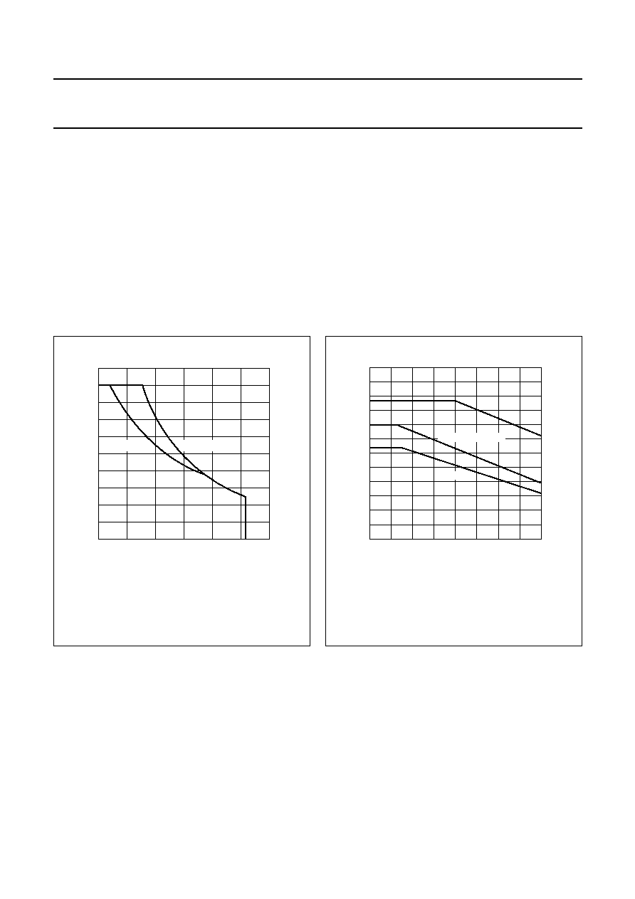
Fig.2 D.C. SOAR.
handbook, halfpage
10
20
30
40
1
0
IC
(A)
MGP272
VCE (V)
0.5
Tmb = 25
°
C
Th = 70
°
C
Fig.3 R.F. power dissipation; V
CE
28 V; f
>
1 MHz.
I Continuous d.c. operation
II Continuous r.f. operation
III Short-time operation during mismatch
handbook, halfpage
0
50
100
30
0
10
20
MGP273
Ptot
(W)
Th (
°
C)
derate by 0.12 W/K
0.1 W/K
THERMAL RESISTANCE
(dissipation = 8 W; T
mb
= 72,4
°
C, i.e. T
h
= 70
°
C)
From junction to mounting base (d.c. dissipation)
R
th j
-
mb(dc)
=
10,7 K/W
From junction to mounting base (r.f. dissipation)
R
th j
-
mb(rf)
=
8,6 K/W
From mounting base to heatsink
R
th mb
-
h
=
0,3 K/W

August 1986
4
Philips Semiconductors
Product specification
VHF power transistor
BLV20
CHARACTERISTICS
T
j
= 25
°
C
Note
1. Measured under pulse conditions: t
p
200
µ
s;
0,02.
Collector-emitter breakdown voltage
V
BE
= 0; I
C
= 2 mA
V
(BR)CES
>
65 V
Collector-emitter breakdown voltage
open base; I
C
= 10 mA
V
(BR)CEO
>
36 V
Emitter-base breakdown voltage
open collector; I
E
= 1 mA
V
(BR)EBO
>
4 V
Collector cut-off current
V
BE
= 0; V
CE
= 36 V
I
CES
<
1 mA
Second breakdown energy; L = 25 mH; f = 50 Hz
open base
E
SBO
>
0,5 mJ
R
BE
= 10
E
SBR
>
0,5 mJ
D.C. current gain
(1)
h
FE
typ.
50
I
C
= 0,4 A; V
CE
= 5 V
10 to 100
Collector-emitter saturation voltage
(1)
I
C
= 1,25 A; I
B
= 0,25 A
V
CEsat
typ.
0,8 V
Transition frequency at f = 100 MHz
(1)
-
I
E
= 0,4 A; V
CB
= 28 V
f
T
typ.
600 MHz
-
I
E
= 1,25 A; V
CB
= 28 V
f
T
typ.
520 MHz
Collector capacitance at f = 1 MHz
I
E
= I
e
= 0; V
CB
= 28 V
C
c
typ.
10 pF
Feedback capacitance at f = 1 MHz
I
C
= 50 mA; V
CE
= 28 V
C
re
typ.
7,1 pF
Collector-flange capacitance
C
cf
typ.
2 pF
August 1986
5
Philips Semiconductors
Product specification
VHF power transistor
BLV20
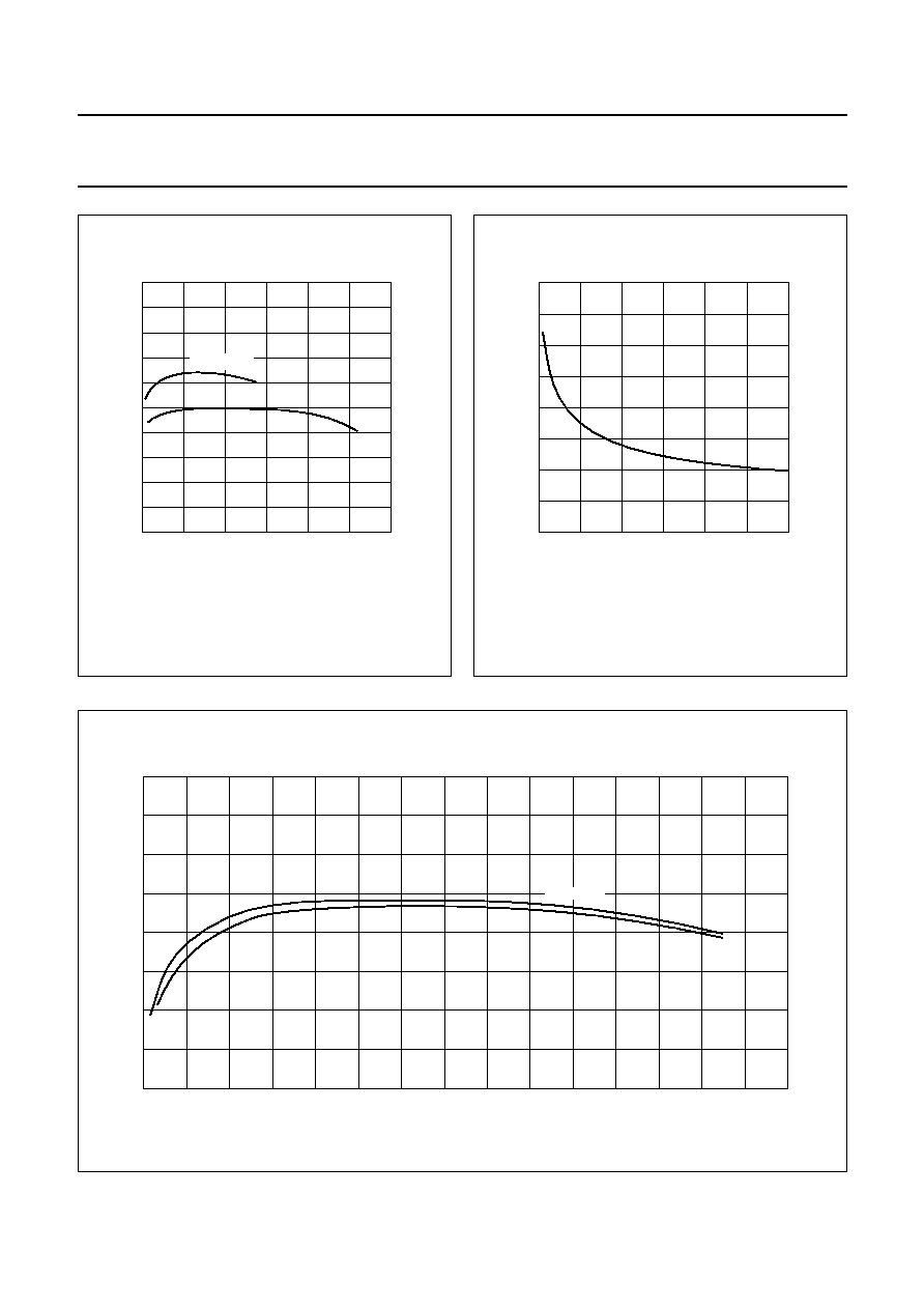
Fig.4 Typical values; T
j
= 25
°
C.
handbook, halfpage
0
0.5
1.5
100
0
MGP274
1
50
hFE
IC (A)
VCE = 28 V
5 V
Fig.5 I
E
= I
e
= 0; f = 1 MHz; T
j
= 25
°
C.
handbook, halfpage
0
10
20
30
40
30
10
0
20
MGP275
Cc
(pF)
VCB (V)
typ
Fig.6 Typical values; f = 100 MHz; T
j
= 25
°
C.
handbook, full pagewidth
1.5
1000
0
0
MGP276
500
1
0.5
VCB = 28 V
-
IE (A)
fT
(MHz)
20 V