 | –≠–ª–µ–∫—Ç—Ä–æ–Ω–Ω—ã–π –∫–æ–º–ø–æ–Ω–µ–Ω—Ç: BLW81 | –°–∫–∞—á–∞—Ç—å:  PDF PDF  ZIP ZIP |
Document Outline
- DESCRIPTION
- QUICK REFERENCE DATA
- PIN CONFIGURATION
- PINNING - SOT122A.
- RATINGS
- THERMAL RESISTANCE
- CHARACTERISTICS
- APPLICATION INFORMATION
- Measuring conditions for R.F. SOAR
- PACKAGE OUTLINE
- DEFINITIONS
- LIFE SUPPORT APPLICATIONS

DATA SHEET
Product specification
March 1993
DISCRETE SEMICONDUCTORS
BLW81
UHF power transistor
March 1993
2
Philips Semiconductors
Product specification
UHF power transistor
BLW81
DESCRIPTION
N-P-N silicon planar epitaxial
transistor intended for transmitting
applications in class-A, B or C in the
u.h.f. and v.h.f. range for a nominal
supply voltages up to 13,5 V.
The resistance stabilization of the
transistor provides protection against
device damage at severe load
mismatch conditions.
The transistor is housed in a
1
/
4
"
capstan envelope with a ceramic cap.
QUICK REFERENCE DATA
R.F. performance up to T
h
= 25
∞
C in an unneutralized common-emitter class-B circuit
MODE OF OPERATION
V
CE
V
f
MHz
P
L
W
G
p
dB
%
z
i
Y
L
mS
c.w.
12,5
470
10
>
6,0
>
60
1,3
+
j2,5
150
-
j66
c.w.
12,5
175
10
typ. 13,5
typ. 60
1,2
-
j0,6
140
-
j80
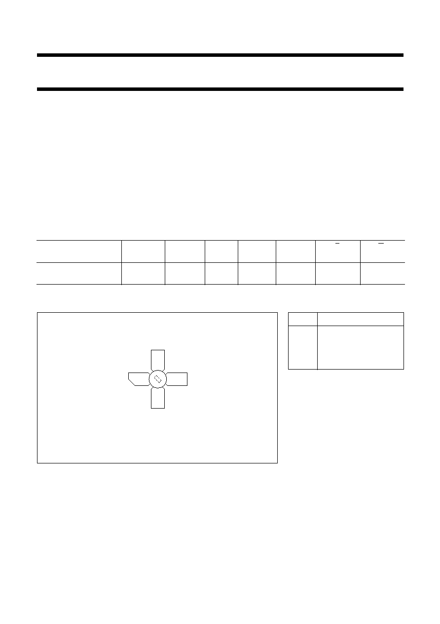
PIN CONFIGURATION
Fig.1 Simplified outline. SOT122A.
handbook, halfpage
Top view
MBK187
3
1
2
4
PINNING - SOT122A.
PIN
DESCRIPTION
1
collector
2
emitter
3
base
4
emitter
PRODUCT SAFETY This device incorporates beryllium oxide, the dust of which is toxic. The device is entirely
safe provided that the BeO disc is not damaged.

March 1993
3
Philips Semiconductors
Product specification
UHF power transistor
BLW81
RATINGS
Limiting values in accordance with the Absolute Maximum System (IEC 134)
Collector-emitter voltage (V
BE
= 0)
peak value
V
CESM
max
36 V
Collector-emitter voltage (open base)
V
CEO
max
17 V
Emitter-base voltage (open collector)
V
EBO
max
4 V
Collector current (d.c. or average)
I
C
max
2,5 A
Collector current (peak value); f
>
1 MHz
I
CM
max
7,5 A
R.F. power dissipation (f
>
1 MHz); T
mb
= 25
∞
C
P
tot
max
40 W
Storage temperature
T
stg
-
65 to
+
150
∞
C
Operating junction temperature
T
j
max
200
∞
C
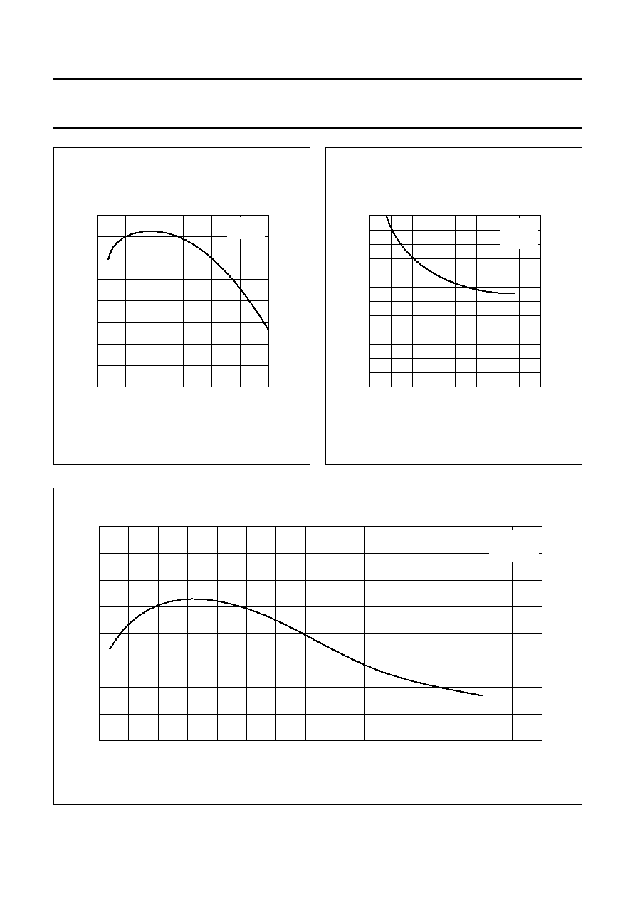
Fig.2
1
10
10
2
handbook, halfpage
MGP573
10
1
Th = 70
∞
C
Tmb = 25
∞
C
VCE (V)
IC
(A)
Fig.3
handbook, halfpage
0
50
100
0
50
MGP574
40
30
10
20
Th (
∞
C)
Prf
(W)
short time operation
during
mismatch
continuous operation
derate by
0.204 W/K
r.f. power dissipation
VCE
16.5 V
f
>
1 MHz
THERMAL RESISTANCE
From junction to mounting base
R
th j-mb
=
4,3 K/W
From mounting base to heatsink
R
th mb-h
=
0,6 K/W

March 1993
4
Philips Semiconductors
Product specification
UHF power transistor
BLW81
CHARACTERISTICS
T
j
= 25
∞
C
Note
1. Measured under pulse conditions: t
p
200
µ
s;
0,02.
Breakdown voltages
Collector-emitter voltage
V
BE
= 0; I
C
= 25 mA
V
(BR)CES
>
36 V
Collector-emitter voltage
open base; I
C
= 100 mA
V
(BR)CEO
>
17 V
Emitter-base voltage
open collector; I
E
= 10 mA
V
(BR)EBO
>
4 V
Collector cut-off current
V
BE
= 0; V
CE
= 17 V
I
CES
<
10 mA
D.C. current gain
(1)
I
C
= 1,25 A; V
CE
= 5 V
h
FE
>
10
typ
35
Collector-emitter saturation voltage
(1)
I
C
= 3,75 A; I
B
= 0,75 A
V
CEsat
typ
0,75 V
Transition frequency at f = 500 MHz
(1)
I
C
= 1,25 A; V
CE
= 12,5 V
f
T
typ
1,3 GHz
I
C
= 3,75 A; V
CE
= 12,5 V
f
T
typ
0,9 GHz
Collector capacitance at f = 1 MHz
I
E
= I
e
= 0; V
CB
= 12,5 V
C
c
typ
34 pF
Feedback capacitance at f = 1 MHz
I
C
= 100 mA; V
CE
= 12,5 V
C
re
typ
18 pF
Collector-stud capacitance
C
cs
typ
1,2 pF
March 1993
5
Philips Semiconductors
Product specification
UHF power transistor
BLW81
Fig.4
handbook, halfpage
0
0
2.5
7.5
40
30
10
20
MGP575
5
IC (A)
hFE
typ
VCE = 5 V
Tj = 25
∞
C
Fig.5
handbook, halfpage
0
10
20
60
0
40
MGP576
20
VCB (V)
Cc
(pF)
typ
IE = Ie = 0
f = 1 MHz
Tj = 25
∞
C
Fig.6
handbook, full pagewidth
7.5
2
MGP577
0
0
2.5
1.5
0.5
1
5
IC (A)
fT
(GHz)
typ
VCE = 12.5 V
f = 500 MHz
Tj = 25
∞
C