 | –≠–ª–µ–∫—Ç—Ä–æ–Ω–Ω—ã–π –∫–æ–º–ø–æ–Ω–µ–Ω—Ç: BLW83 | –°–∫–∞—á–∞—Ç—å:  PDF PDF  ZIP ZIP |

DATA SHEET
Product specification
August 1986
DISCRETE SEMICONDUCTORS
BLW83
HF/VHF power transistor

August 1986
2
Philips Semiconductors
Product specification
HF/VHF power transistor
BLW83
DESCRIPTION
N-P-N silicon planar epitaxial
transistor for use in transmitting
amplifiers operating in the h.f. and
v.h.f. bands, with a nominal supply
voltage of 28 V. The transistor is
specified for s.s.b. applications as
linear amplifier in class-A and AB.
The device is resistance stabilized
and is guaranteed to withstand
severe load mismatch conditions.
Matched h
FE
groups are available on
request.
It has a 3/8" flange envelope with a
ceramic cap. All leads are isolated
from the flange.
QUICK REFERENCE DATA
R.F. performance
MODE OF OPERATION
V
CE
V
f
MHz
P
L
W
G
p
dB
dt
%
I
C
A
d
3
dB
T
h
∞
C
s.s.b. (class-A)
26
1,6
-
28
0
-
10 (P.E.P.)
>
20
-
1,35
< -
40
70
s.s.b. (class-AB)
28
1,6
-
28
3
-
30 (P.E.P.)
typ. 21
typ. 40
typ. 1,34
typ.
-
30
25
PIN CONFIGURATION
handbook, halfpage
e
c
b
MBB012
Fig.1 Simplified outline and symbol.
halfpage
1
2
3
4
MSB057
PINNING - SOT123
PIN
DESCRIPTION
1
collector
2
emitter
3
base
4
emitter
PRODUCT SAFETY This device incorporates beryllium oxide, the dust of which is toxic. The device is entirely
safe provided that the BeO disc is not damaged.
August 1986
3
Philips Semiconductors
Product specification
HF/VHF power transistor
BLW83
RATINGS
Limiting values in accordance with the Absolute Maximum System (IEC 134)
Collector-emitter voltage (V
BE
= 0)
peak value
V
CESM
max.
65 V
Collector-emitter voltage (open base)
V
CEO
max.
36 V
Emitter-base voltage (open-collector)
V
EBO
max.
4 V
Collector current (average)
I
C(AV)
max.
3 A
Collector current (peak value); f
>
1 MHz
I
CM
max.
9 A
R.F. power dissipation (f
>
1 MHz); T
mb
= 25
∞
C
P
rf
max.
76 W
Storage temperature
T
stg
-
65 to
+
150
∞
C
Operating junction temperature
T
j
max.
200
∞
C
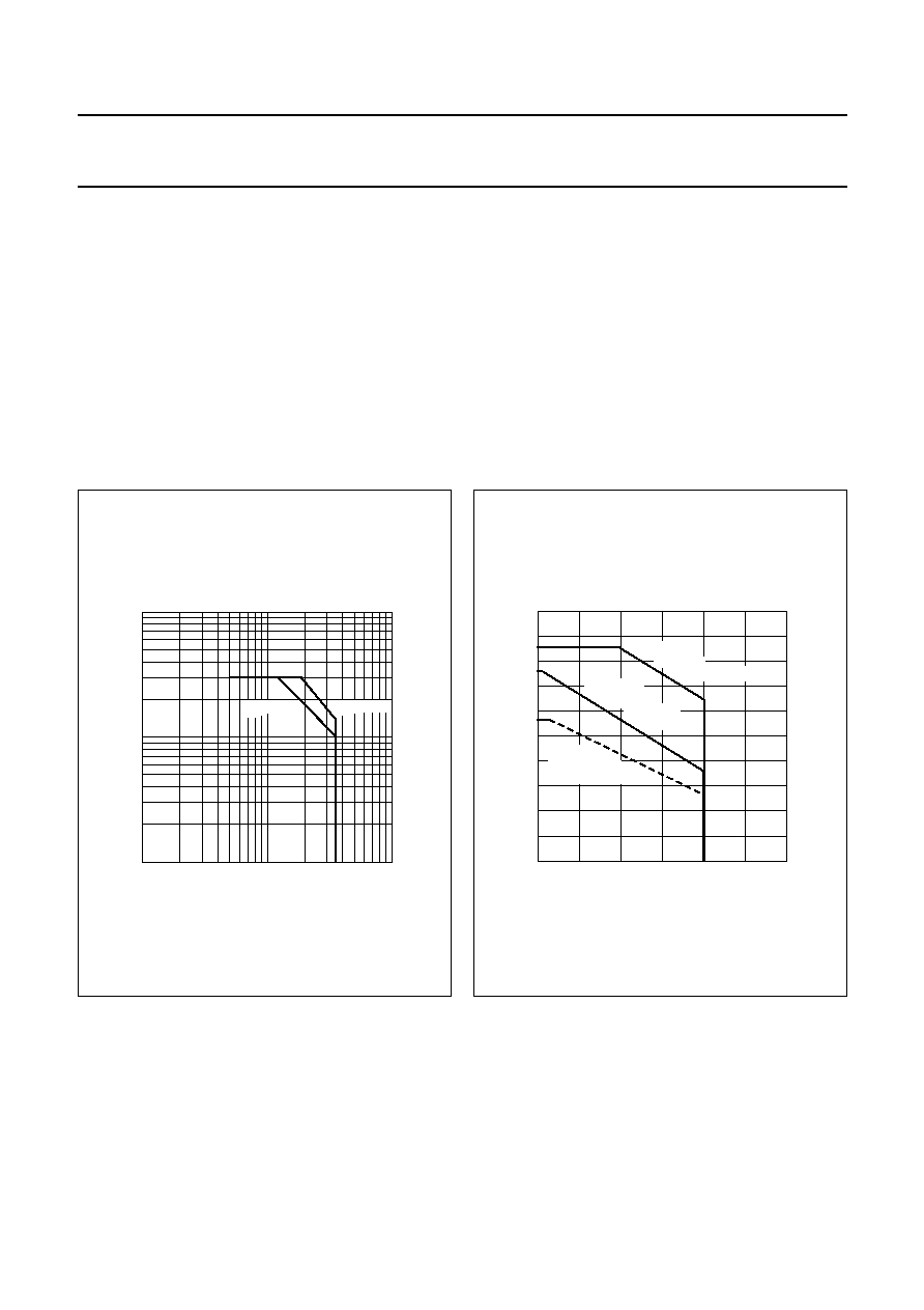
Fig.2 D.C. SOAR.
handbook, halfpage
MGP586
10
1
10
-
1
1
10
10
2
IC
(A)
VCE (V)
Th = 70
∞
C
Tmb = 25
∞
C
Fig.3 R.F. power dissipation; V
CE
28 V; f
1 MHz.
handbook, halfpage
0
50
100
150
100
0
50
MGP587
Prf
(W)
Th (
∞
C)
continuous
d.c. operation
derate by 0.32 W/K
continuous
r.f. operation
derate by
0.42 W/K
short-time
operation
during mismatch
THERMAL RESISTANCE
(dissipation = 35 W; T
mb
= 80
∞
C, i.e. T
h
= 70
∞
C)
From junction to mounting base (d.c. dissipation)
R
th j-mb(dc)
=
3,15 K/W
From junction to mounting base (r.f. dissipation)
R
th j-mb(rf)
=
2,35 K/W
From mounting base to heatsink
R
th mb-h
=
0,3 K/W

August 1986
4
Philips Semiconductors
Product specification
HF/VHF power transistor
BLW83
CHARACTERISTICS
T
j
= 25
∞
C unless otherwise specified
Note
1. Measured under pulse conditions: t
p
200
µ
s;
0,02.
Collector-emitter breakdown voltage
V
BE
= 0; I
C
= 10 mA
V
(BR)CES
>
65 V
Collector-emitter breakdown voltage
open base; I
C
= 50 mA
V
(BR)CEO
>
36 V
Emitter-base breakdown voltage
open collector; I
E
= 10 mA
V
(BR)EBO
>
4 V
Collector cut-off current
V
BE
= 0; V
CE
= 36 V
I
CES
<
4 mA
Second breakdown energy; L = 25 mH; f = 50 Hz
open base
E
SBO
>
8 mJ
R
BE
= 10
E
SBR
>
8 mJ
D.C. current gain
(1)
typ.
50
I
C
= 1,25 A; V
CE
= 5 V
h
FE
10 to 100
D.C. current gain ratio of matched devices
(1)
I
C
= 1,25 A; V
CE
= 5 V
h
FE1
/h
FE2
<
1,2
Collector-emitter saturation voltage
(1)
I
C
= 3,75 A; I
B
= 0,75 A
V
CEsat
typ.
1,5 V
Transition frequency at f = 100 MHz
(1)
-
I
E
= 1,25 A; V
CB
= 28 V
f
T
typ.
530 MHz
-
I
E
= 3,75 A; V
CB
= 28 V
f
T
typ.
530 MHz
Collector capacitance at f = 1 MHz
I
E
= I
e
= 0; V
CB
= 28 V
C
c
typ.
50 pF
Feedback capacitance at f = 1 MHz
I
C
= 100 mA; V
CE
= 28 V
C
re
typ.
31 pF
Collector-flange capacitance
C
cf
typ.
2 pF
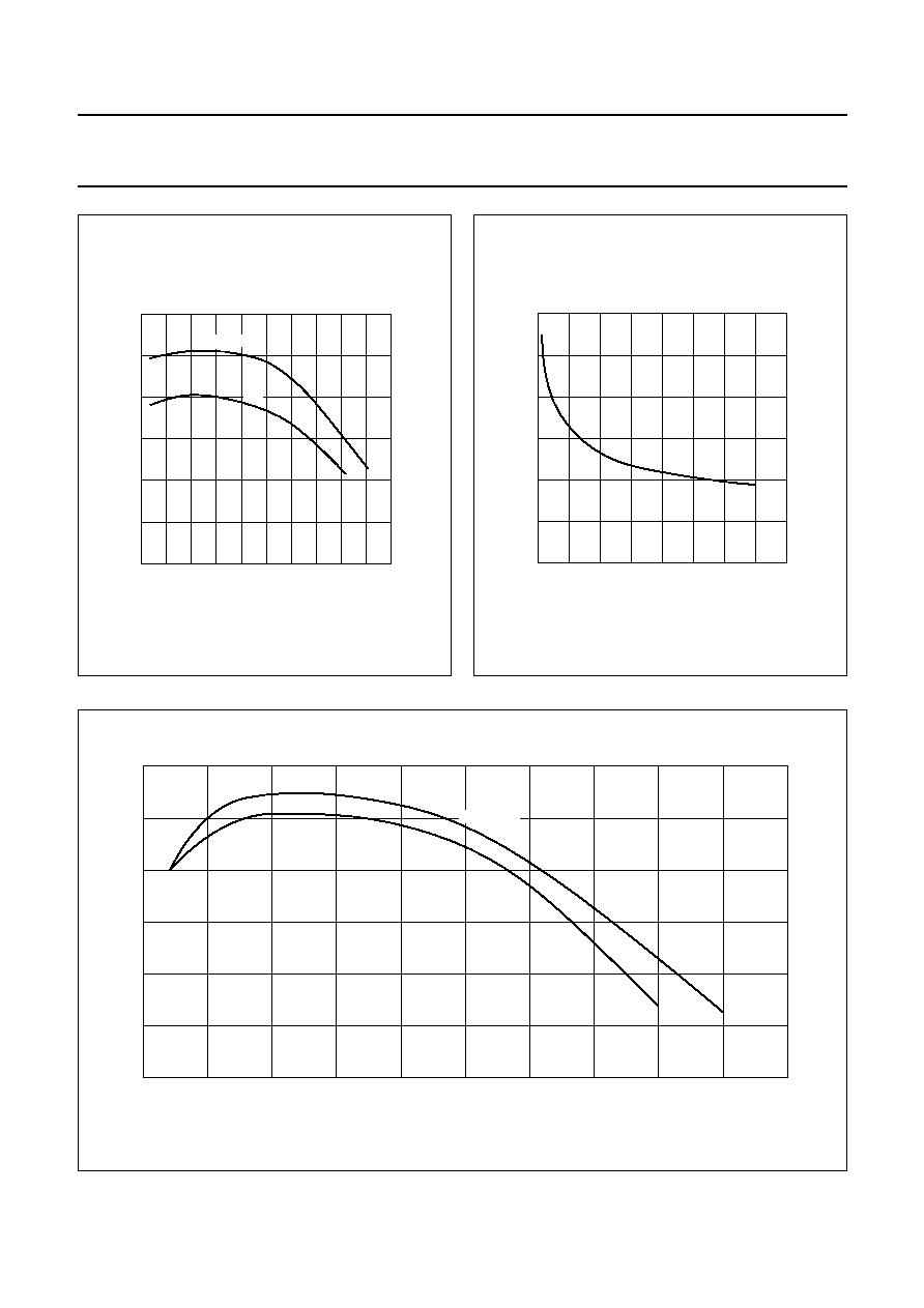
Fig.4 Typical values; V
CE
= 28 V.
handbook, halfpage
0
1
2
3
1
0
2
MGP588
IC
(A)
VBE (V)
Th = 70
∞
C
25
∞
C
August 1986
5
Philips Semiconductors
Product specification
HF/VHF power transistor
BLW83
Fig.5 Typical values; T
j
= 25
∞
C.
handbook, halfpage
0
5
10
50
0
25
75
MGP589
VCE = 28 V
hFE
IC (A)
5 V
Fig.6 I
E
= I
e
= 0; f = 1 MHz; T
j
= 25
∞
C.
handbook, halfpage
0
20
40
150
50
0
100
MGP590
Cc
(pF)
VCB (V)
typ
Fig.7 Typical values; f = 100 MHz; T
j
= 25
∞
C.
handbook, full pagewidth
10
6
600
0
0
2
8
MGP591
4
200
400
fT
(MHz)
-
IE (A)
VCB = 28 V
15 V