
1.
Product profile
1.1 General description
Passivated thyristors in a SOT186A full pack plastic package.
1.2 Features
1.3 Applications
1.4 Quick reference data
2.
Pinning information
BT151X series
Thyristors
Rev. 04 -- 9 June 2004
Product data sheet
s
High thermal cycling performance
s
Isolated mounting base.
s
High bidirectional blocking voltage
capability
s
Motor control
s
Industrial and domestic lighting, heating
and static switching.
s
V
DRM
, V
RRM
800 V (BT151X-800)
s
I
T(RMS)
12 A
s
V
DRM
, V
RRM
650 V (BT151X-650)
s
I
T(AV)
7.5 A
s
V
DRM
, V
RRM
500 V (BT151X-500)
s
I
TSM
120 A.
Table 1:
Discrete pinning
Pin
Description
Simplified outline
Symbol
1
cathode (k)
SOT186A (TO-220)
2
anode (a)
3
gate (g)
mb
mounting base; isolated
1
mb
2 3
sym037

9397 750 13162
© Koninklijke Philips Electronics N.V. 2004. All rights reserved.
Product data sheet
Rev. 04 -- 9 June 2004
2 of 11
Philips Semiconductors
BT151X series
Thyristors
3.
Ordering information
4.
Limiting values
[1]
Although not recommended, off-state voltages up to 800 V may be applied without damage, but the thyristor may switch to the on-state.
The rate of rise of current should not exceed 15 A/
µ
s.
Table 2:
Ordering information
Type number
Package
Name
Description
Version
BT151X-500
-
plastic single-ended package; isolated heatsink mounted; 1 mounting hole;
3 lead TO-220 `full pack'
SOT186A
BT151X-650
BT151X-800
Table 3:
Limiting values
In accordance with the Absolute Maximum Rating System (IEC 60134).
Symbol
Parameter
Conditions
Min
Max
Unit
V
DRM
, V
RRM
repetitive peak off-state voltage
BT151X-500
[1]
-
500
V
BT151X-650
[1]
-
650
V
BT151X-800
-
800
V
I
T(AV)
average on-state current
half sinewave;
T
hs
69
∞
C;
Figure 1
-
7.5
A
I
T(RMS)
RMS on-state current
all conduction angles;
Figure 4
and
Figure 5
-
12
A
I
TSM
non-repetitive peak on-state current
half sinewave;
T
j
= 25
∞
C prior to
surge;
Figure 2
and
Figure 3
t = 10 ms
-
120
A
t = 8.3 ms
-
132
A
I
2
t
I
2
t for fusing
t = 10 ms
-
72
A
2
s
dI
T
/dt
repetitive rate of rise of on-state
current after triggering
I
TM
= 20 A; I
G
= 50 mA;
dI
G
/dt 50 mA/
µ
s
-
50
A/
µ
s
I
GM
peak gate current
-
2
A
V
RGM
peak reverse gate voltage
-
5
V
P
GM
peak gate power
-
5
W
P
G(AV)
average gate power
over any 20 ms period
-
0.5
W
T
stg
storage temperature
-
40
+150
∞
C
T
j
junction temperature
-
125
∞
C

9397 750 13162
© Koninklijke Philips Electronics N.V. 2004. All rights reserved.
Product data sheet
Rev. 04 -- 9 June 2004
3 of 11
Philips Semiconductors
BT151X series
Thyristors
a = form factor = I
T(RMS)
/I
T(AV)
.
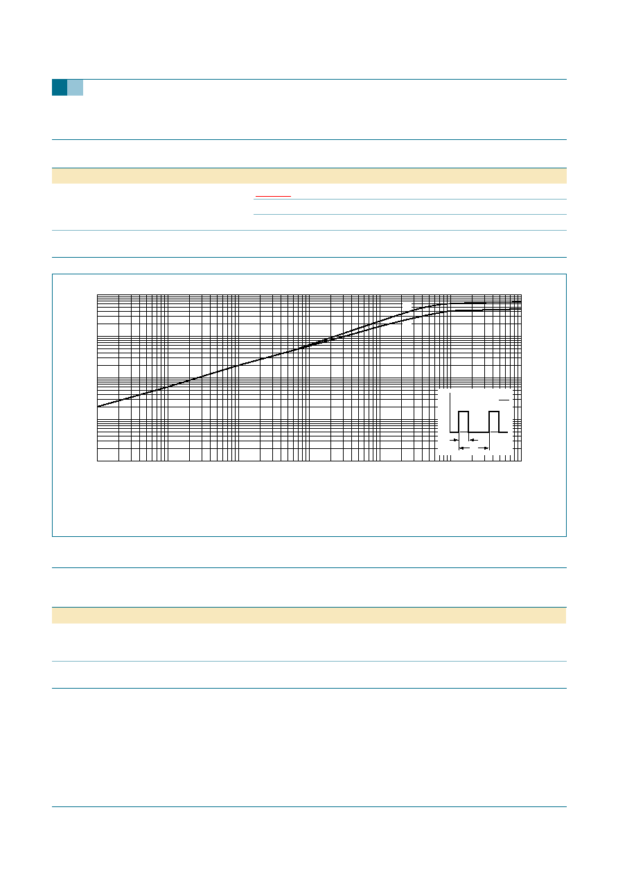
Fig 1.
Total power dissipation as a function of average on-state current; maximum values.
f = 50 Hz.
Fig 2.
Non-repetitive peak on-state current as a function of the number of sinusoidal current cycles; maximum
values.
I
T(AV)
(A)
0
8
6
4
2
001aaa961
5
10
15
P
tot
(W)
0
102.5
80
57.5
T
hs(max)
(
∞
C)
125
a =
1.57
4
2.8
2.2
1.9
conduction
angle
(degrees)
form
factor
a
30
60
90
120
180
4
2.8
2.2
1.9
1.57
001aaa957
80
40
120
160
I
TSM
(A)
0
n
1
10
3
10
2
10
t
p
T
j
initial = 25
∞
C max
I
T
I
TSM
t

9397 750 13162
© Koninklijke Philips Electronics N.V. 2004. All rights reserved.
Product data sheet
Rev. 04 -- 9 June 2004
4 of 11
Philips Semiconductors
BT151X series
Thyristors
t
p
10 ms.
Fig 3.
Non-repetitive peak on-state current as a function of pulse width; maximum values.
f = 50 Hz; T
hs
87
∞
C.
Fig 4.
RMS on-state current as a function of surge
duration; maximum values.
Fig 5.
RMS on-state current as a function of heatsink
temperature; maximum values.
001aaa956
t
p
(s)
10
-
5
10
-
2
10
-
3
10
-
4
10
2
10
3
I
TSM
(A)
10
dl
T
/dt limit
t
p
T
j
initial = 25
∞
C max
I
T
I
TSM
t
surge duration (s)
10
-
2
10
1
10
-
1
001aaa955
10
15
5
20
25
I
T(RMS)
(A)
0
T
hs
(
∞
C)
-
50
150
100
0
50
001aaa960
8
4
12
16
I
T(RMS)
(A)
0
9397 750 13162
© Koninklijke Philips Electronics N.V. 2004. All rights reserved.
Product data sheet
Rev. 04 -- 9 June 2004
5 of 11
Philips Semiconductors
BT151X series
Thyristors
5.
Thermal characteristics
6.
Isolation characteristics
Table 4:
Thermal characteristics
Symbol
Parameter
Conditions
Typ
Max
Unit
R
th(j-hs)
thermal resistance from
junction to heatsink
Figure 6
with heatsink compound
-
4.5
K/W
without heatsink compound
-
6.5
K/W
R
th(j-a)
thermal resistance from
junction to ambient
in free air
55
-
K/W
(1) Without heatsink compound.
(2) With heatsink compound.
Fig 6.
Transient thermal impedance as a function of pulse width.
001aaa964
10
-
1
10
-
2
1
10
Z
th(j-hs)
(K/W)
10
-
3
t
p
(s)
10
-
5
1
10
10
-
1
10
-
2
10
-
4
10
-
3
t
p
t
p
T
P
t
T
=
(2)
(1)
Table 5:
Isolation limiting values and characteristics
T
hs
= 25
∞
C unless otherwise specified
Symbol
Parameter
Conditions
Typ
Max
Unit
V
isol
RMS isolation voltage from all
three terminals to external
heatsink
f = 50 to 60 Hz; sinusoidal
waveform; R.H.
65%; clean and
dust free
-
2500
V
C
isol
capacitance from pin 2 to
external heatsink
f = 1 MHz
10
-
pF