
Philips Semiconductors
Product specification
Rectifier diodes
BY229 series
fast, soft-recovery
FEATURES
SYMBOL
QUICK REFERENCE DATA
∑ Low forward volt drop
V
R
= 200 V/ 400 V/ 600 V/800 V
∑ Fast switching
∑ Soft recovery characteristic
I
F(AV)
= 8 A
∑ High thermal cycling performance
∑ Low thermal resistance
I
FSM
60 A
t
rr
135 ns
GENERAL DESCRIPTION
PINNING
SOD59 (TO220AC)
Glass-passivated double diffused
PIN
DESCRIPTION
rectifier
diodes
featuring
low
forward voltage drop, fast reverse
1
cathode
recovery
and
soft
recovery
characteristic. The devices are
2
anode
intended for use in TV receivers,
monitors and switched mode power
tab
cathode
supplies.
The BY229 series is supplied in the
conventional
leaded
SOD59
(TO220AC) package.
LIMITING VALUES
Limiting values in accordance with the Absolute Maximum System (IEC 134).
SYMBOL
PARAMETER
CONDITIONS
MIN.
MAX.
UNIT
BY229
-200
-400
-600
-800
V
RSM
Peak non-repetitive reverse
-
200
400
600
800
V
voltage
V
RRM
Peak repetitive reverse voltage
-
200
400
600
800
V
V
RWM
Crest working reverse voltage
-
150
300
500
600
V
V
R
Continuous reverse voltage
-
150
300
500
600
V
I
F(AV)
Average forward current
1
square wave;
-
8
A
= 0.5;
T
mb
122 ∞C
sinusoidal;
-
7
A
a = 1.57;
T
mb
125 ∞C
I
F(RMS)
RMS forward current
-
11
A
I
FRM
Repetitive peak forward current t = 25
µ
s;
= 0.5;
-
16
A
T
mb
122 ∞C
I
FSM
Non-repetitive peak forward
t = 10 ms
-
60
A
current.
t = 8.3 ms
-
66
A
sinusoidal;
T
j
= 150 ∞C prior to
surge; with
reapplied V
RWM(max)
I
2
t
I
2
t for fusing
t = 10 ms
-
18
A
2
s
T
stg
Storage temperature
-40
150
∞C
T
j
Operating junction temperature
-
150
∞C
k
a
1
2
1
tab
2
1 Neglecting switching and reverse current losses.
September 1998
1
Rev 1.200

Philips Semiconductors
Product specification
Rectifier diodes
BY229 series
fast, soft-recovery
THERMAL RESISTANCES
SYMBOL
PARAMETER
CONDITIONS
MIN.
TYP.
MAX.
UNIT
R
th j-mb
Thermal resistance junction to
-
-
2.0
K/W
mounting base
R
th j-a
Thermal resistance junction to
in free air.
-
60
-
K/W
ambient
STATIC CHARACTERISTICS
T
j
= 25 ∞C unless otherwise stated
SYMBOL
PARAMETER
CONDITIONS
MIN.
TYP.
MAX.
UNIT
V
F
Forward voltage
I
F
= 20 A
-
1.5
1.85
V
I
R
Reverse current
V
R
= V
RWM
; T
j
= 125 ∞C
-
0.1
0.4
mA
DYNAMIC CHARACTERISTICS
T
j
= 25 ∞C unless otherwise stated
SYMBOL
PARAMETER
CONDITIONS
MIN.
TYP.
MAX.
UNIT
t
rr
Reverse recovery time
I
F
= 1 A; V
R
> 30 V; -dI
F
/dt = 50 A/
µ
s
-
100
135
ns
Q
s
Reverse recovery charge
I
F
= 2 A; V
R
> 30 V; -dI
F
/dt = 20 A/
µ
s
-
0.5
0.7
µ
C
dI
R
/dt
Maximum slope of the reverse
I
F
= 2 A; -dI
F
/dt = 20 A/
µ
s
-
50
60
A/
µ
s
recovery current
September 1998
2
Rev 1.200
Philips Semiconductors
Product specification
Rectifier diodes
BY229 series
fast, soft-recovery
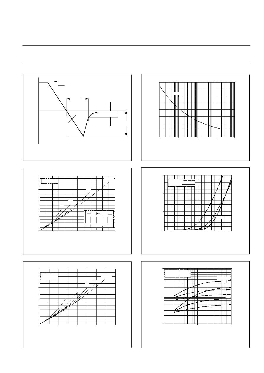
Fig.1. Definition of t
rr
, Q
s
and I
rrm
Fig.2. Maximum forward dissipation, P
F
= f(I
F(AV)
);
square wave current waveform; parameter D = duty
cycle = t
p
/T.
Fig.3. Maximum forward dissipation, P
F
= f(I
F(AV)
);
sinusoidal current waveform; parameter a = form
factor = I
F(RMS)
/I
F(AV)
.
Fig.4. Maximum non-repetitive rms forward current.
I
F
= f(t
p
); sinusoidal current waveform; T
j
= 150∞C prior
to surge with reapplied V
RWM
.
Fig.5. Typical and maximum forward characteristic;
I
F
= f(V
F
); parameter T
j
Fig.6. Maximum Q
s
at T
j
= 25∞C and 150∞C
100%
time
dI
dt
F
I
R
I
F
I
rrm
trr
25%
Qs
1ms
10ms
0.1s
1s
10s
tp / s
IFS(RMS) / A
BY229
80
70
60
50
40
30
20
10
0
IFSM
0
1
BY229F
VF / V
IF / A
30
20
10
0
2
0.5
1.5
max
typ
Tj = 150 C
Tj = 25 C
0
2
4
6
8
10
12
BY329
IF(AV) / A
PF / W
20
15
10
5
0
Tmb(max) / C
150
110
120
130
140
0.5
0.2
0.1
D = 1.0
D =
t
p
t
p
T
T
I
t
Vo = 1.25 V
Rs = 0.03 Ohms
1
100
BY329
-dIF/dt (A/us)
Qs / uC
10
1
0.1
10
2 A
IF = 10 A
10 A
1 A
1 A
2 A
Tj = 150 C
Tj = 25 C
0
2
4
6
8
BY329
IF(AV) / A
PF / W
15
10
5
0
4
2.8
2.2
1.9
a = 1.57
Tmb(max) / C
150
120
130
140
Vo = 1.25 V
Rs = 0.03 Ohms
September 1998
3
Rev 1.200

Philips Semiconductors
Product specification
Rectifier diodes
BY229 series
fast, soft-recovery
Fig.7. Maximum t
rr
measured to 25% of I
rrm
; T
j
= 25∞C
and 150∞C
Fig.8. Typical junction capacitance C
d
at f = 1 MHz
;
T
j
= 25∞C
Fig.9. Transient thermal impedance Z
th
= f(t
p
)
1
10
100
BY329
-dIF/dt (A/us)
trr / ns
1000
100
10
1 A
IF = 10 A
Tj = 150 C
Tj = 25 C
10A
1A
1us
10us
100us
1ms
10ms
100ms
1s
10s
0.001
0.01
0.1
1
10
BY229
pulse width, tp (s)
Transient thermal impedance, Zth j-mb (K/W)
D =
t
p
t
p
T
T
P
t
D
1
100
100
10
1
10
1000
BY329
Cd / pF
VR / V
September 1998
4
Rev 1.200

Philips Semiconductors
Product specification
Rectifier diodes
BY229 series
fast, soft-recovery
MECHANICAL DATA
Dimensions in mm
Net Mass: 2 g
Fig.10. SOD59 (TO220AC). pin 1 connected to mounting base.
Notes
1. Refer to mounting instructions for TO220 envelopes.
2. Epoxy meets UL94 V0 at 1/8".
10,3
max
3,7
2,8
3,0
3,0 max
not tinned
1,3
max
(2x)
2,4
0,6
4,5
max
5,9
min
15,8
max
1,3
0,9 max (2x)
13,5
min
5,08
1
2
September 1998
5
Rev 1.200