Document Outline
- DESCRIPTION
- FAMILY DATA, IDD LIMITS category MSI
- PINNING
- FREQUENCY SELECTION TABLE
- FUNCTION TABLE
- Timing component limitations
- DC CHARACTERISTICS
- AC CHARACTERISTICS

DATA SHEET
Product specification
File under Integrated Circuits, IC04
January 1995
INTEGRATED CIRCUITS
HEF4541B
MSI
Programmable timer
For a complete data sheet, please also download:
∑
The IC04 LOCMOS HE4000B Logic
Family Specifications HEF, HEC
∑
The IC04 LOCMOS HE4000B Logic
Package Outlines/Information HEF, HEC

January 1995
2
Philips Semiconductors
Product specification
Programmable timer
HEF4541B
MSI
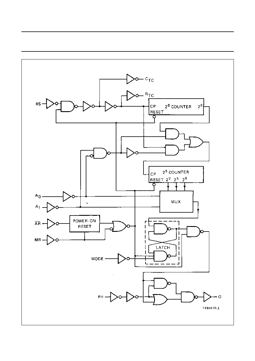
DESCRIPTION
The HEF4541B is a programmable timer which consists of
a 16-stage binary counter, an integrated oscillator to be
used with external timing components, an automatic
power-on reset and output control logic. The frequency of
the oscillator is determined by the external components
R
t
and C
t
within the frequency range 1 Hz to 100 kHz. This
oscillator may be replaced by an external clock signal at
input RS, the timer advances on the positive-going
transition of RS. A LOW on the auto reset input (AR) and
a LOW on the master reset input (MR) enables the internal
power-on reset. A HIGH level at input MR resets the
counter independent on all other inputs. Resetting
disables the oscillator to provide no active power
dissipation.
A HIGH at input AR turns off the power-on reset to provide
a low quiescent power dissipation of the timer. The
16-stage counter divides the oscillator frequency by
2
8
, 2
10
, 2
13
or 2
16
depending on the state of the address
inputs (A
0
, A
1
). The divided oscillator frequency is
available at output O. The phase input (PH) features a
complementary output signal. If the mode select input
(MODE) is LOW or HIGH the timer can be used
respectively as a single transition timer or 2
n
frequency
divider.
Fig.1 Functional diagram.
Fig.2 Pinning diagram.
FAMILY DATA, I
DD
LIMITS category MSI
See Family Specifications
HEF4541BP(N):
14-lead DIL; plastic
(SOT27-1)
HEF4541BD(F):
14-lead DIL; ceramic (cerdip)
(SOT73)
HEF4541BT(D):
14-lead SO; plastic
(SOT108-1)
( ): Package Designator North America
January 1995
3
Philips Semiconductors
Product specification
Programmable timer
HEF4541B
MSI
Fig.3 Logic diagram.

January 1995
4
Philips Semiconductors
Product specification
Programmable timer
HEF4541B
MSI
PINNING
FREQUENCY SELECTION TABLE
A
0
, A
1
address inputs
MODE
mode select input
AR
auto reset input
MR
master reset input
PH
phase input
R
TC
external resistor connection (R
t
)
C
TC
external capacitor connection (C
t
)
RS
external resistor connection (R
S
) or
external clock input
A
0
A
1
NUMBER OF
COUNTER STAGES n
L
L
13
8 192
L
H
10
1 024
H
L
8
256
H
H
16
65 536
f
osc
f
out
---------
2
n
=
FUNCTION TABLE
Notes
1. For correct power-on reset, the supply voltage should
be above 8.5 V. For V
DD
< 8.5 V, disable the autoreset
and connect AR to V
DD
.
2. The timer is initialized on a reset pulse and the output
changes state after 2
n-1
counts and remains in that
state (latched). Reset of this latch is obtained by
master reset or by a LOW to HIGH transition on the
MODE input.
H = HIGH state (the more positive voltage)
L = LOW state (the less positive voltage)
X = state is immaterial
INPUTS
MODE
AR
MR
PH
MODE
H
L
X
X
auto reset disabled
L
L
X
X
auto reset enabled
(1)
X
H
X
X
master reset active
X
L
X
H
normal operation selected
division to output
X
L
X
L
single-cycle mode
(2)
X
L
L
X
output initially LOW,
after reset
X
L
H
X
output initially HIGH,
after reset
RC oscillator
Fig.4
External component connection for RC
oscillator; R
S
2 R
t
.
Typical formula for oscillator
frequency:
f
osc
1
2 3
R
t
C
t
◊
◊
,
---------------------------------
=
Timing component limitations
The oscillator frequency is mainly determined by
R
t
C
t
, provided R
t
<< R
S
and R
S
C2 << R
t
C
t
. The function of
R
S
is to minimize the influence of the forward voltage
across the input protection diodes on the frequency. The
stray capacitance C2 should be kept as small as possible.
In consideration of accuracy, C
t
must be larger than the
inherent stray capacitance. R
t
must be larger than the
LOCMOS `ON' resistance in series with it, which typically
is 500
at V
DD
= 5 V, 300
at V
DD
= 10 V and 200
at
V
DD
= 15 V.
The recommended values for these components to
maintain agreement with the typical oscillation formula are:
C
t
100 pF, up to any typical value,
10 k
R
t
1 M
.

January 1995
5
Philips Semiconductors
Product specification
Programmable timer
HEF4541B
MSI
Fig.5 RC oscillator frequency as a function of R
t
and C
t
at V
DD
= 5 to 15 V; T
amb
= 25
∞
C.
C
t
curve at R
t
= 56 k
; R
S
= 120 k
.
- - -
R
t
curve at C
t
= 1 nF; R
S
= 2 R
t
.

January 1995
6
Philips Semiconductors
Product specification
Programmable timer
HEF4541B
MSI
Fig.6
Frequency deviation (
f) as a function of ambient temperature; referenced at : f
osc
at T
amb
= 25
∞
C and
V
DD
= 10 V.
R
t
= 56 k
; C
t
= 1 nF; R
S
= 0.
- - -
R
t
= 56 k
; C
t
= 1 nF; R
S
= 120 k
.

January 1995
7
Philips Semiconductors
Product specification
Programmable timer
HEF4541B
MSI
DC CHARACTERISTICS
V
SS
= 0 V
Note
1. All inputs at 0 V or V
DD
; except input AR = input MR = 0 V (power-on reset active).
AC CHARACTERISTICS
V
SS
= 0 V; T
amb
= 25
∞
C; input transition times
20 ns
Notes
1. where:
f
i
= input frequency (MHz)
f
o
= output frequency (MHz)
C
L
= load capacitance (pF)
V
DD
= supply voltage (V)
C
t
= timing capacitance (pF)
f
osc
= oscillator frequency (MHz)
V
DD
V
V
OL
V
V
OH
V
SYMBOL
T
amb
(
∞
C)
-
40
+
25
+
85
MIN. MAX. MIN.
TYP.
MAX. MIN. MAX.
Supply current
5
-
80
-
20
80
-
230
µ
A
power-on reset
10
I
D
-
750
-
250
600
-
700
µ
A
enabled (note)
15
-
1600
-
500
1300
-
1500
µ
A
Supply voltage for automatic
reset initialization (note)
V
DD
-
-
8,5
5
-
-
-
V
Output current
5
4,6
0,5
-
0,4
-
-
0,3
-
mA
HIGH; C
TC
, R
TC
10
9,5
-
I
OH
1,4
-
1,2
-
-
0,95
-
mA
15
13,5
4,8
-
4,0
-
-
3,2
-
mA
5
2,5
-
I
OH
1,4
-
1,2
-
-
0,95
-
mA
Output current
5
0,4
0,33
-
0,27
-
-
0,20
-
mA
LOW; C
TC
, R
TC
10
0,5
I
OL
1,00
-
0,85
-
-
0,68
-
mA
15
1,5
3,20
-
2,70
-
-
2,30
-
mA
V
DD
V
TYPICAL FORMULA FOR P (
µ
W)
(1)
Dynamic power dissipation
5
1 300
f
i
+
f
o
C
L
V
DD
2
per package
10
5 300
f
i
+
f
o
C
L
V
DD
2
(P)
15
12 000
f
i
+
f
o
C
L
V
DD
2
Total power dissipation
5
1 300
f
osc
+
f
o
C
L
V
DD
2
+
2C
t
V
DD
2
f
osc
+
10 V
DD
when using the
10
5 300
f
osc
+
f
o
C
L
V
DD
2
+
2C
t
V
DD
2
f
osc
+
100 V
DD
on-chip oscillator (P)
15
12 000
f
osc
+
f
o
C
L
V
DD
2
+
2C
t
V
DD
2
f
osc
+
400 V
DD

January 1995
8
Philips Semiconductors
Product specification
Programmable timer
HEF4541B
MSI
AC CHARACTERISTICS
V
SS
= 0 V; T
amb
= 25
∞
C; C
L
= 50 pF; input transition times
20 ns
V
DD
V
SYMBOL
MIN.
TYP.
MAX.
TYPICAL EXTRAPOLATION
FORMULA
Propagation delays
RS
O
2
8
selected
5
t
PHL
;
t
PLH
375
750 ns
348 ns
+
(0,55 ns/pF) C
L
HIGH to LOW
LOW to HIGH
10
150
300 ns
139 ns
+
(0,23 ns/pF) C
L
15
110
220 ns
102 ns
+
(0,16 ns/pF) C
L
RS
O
2
10
selected
5
t
PHL
;
t
PLH
425
850 ns
398 ns
+
(0,55 ns/pF) C
L
HIGH to LOW
LOW to HIGH
10
165
330 ns
154 ns
+
(0,23 ns/pF) C
L
15
120
240 ns
112 ns
+
(0,16 ns/pF) C
L
RS
O
2
13
selected
5
t
PHL
;
t
PLH
510
1020 ns
483 ns
+
(0,55 ns/pF) C
L
HIGH to LOW
LOW to HIGH
10
190
380 ns
179 ns
+
(0,23 ns/pF) C
L
15
135
270 ns
127 ns
+
(0,16 ns/pF) C
L
RS
O
2
16
selected
5
t
PHL
;
t
PLH
575
1150 ns
548 ns
+
(0,55 ns/pF) C
L
HIGH to LOW
LOW to HIGH
10
210
420 ns
199 ns
+
(0,23 ns/pF) C
L
15
150
300 ns
142 ns
+
(0,16 ns/pF) C
L
Minimum clock
5
60
30
ns
pulse width; LOW
10
t
WRSL
30
15
ns
15
24
12
ns
Minimum reset
5
60
30
ns
pulse width; HIGH
10
t
WMRH
30
15
ns
15
24
12
ns
Maximum clock
5
8
16
MHz
pulse frequency
10
f
max
15
30
MHz
15
18
36
MHz
Oscillator frequency
5
90
kHz
R
t
= 5 k
10
f
osc
90
kHz
C
t
= 1 nF
15
90
kHz
R
S
= 10 k
Oscillator frequency
5
8
kHz
R
t
= 56 k
10
f
osc
8
kHz
C
t
= 1 nF
15
8
kHz
R
S
= 120 k