 | –≠–ª–µ–∫—Ç—Ä–æ–Ω–Ω—ã–π –∫–æ–º–ø–æ–Ω–µ–Ω—Ç: PMBZ5249B | –°–∫–∞—á–∞—Ç—å:  PDF PDF  ZIP ZIP |

DATA SHEET
Product specification
Supersedes data of 1996 Apr 26
1999 May 17
DISCRETE SEMICONDUCTORS
PMBZ5226B to PMBZ5257B
Voltage regulator diodes
book, halfpage
M3D088

1999 May 17
2
Philips Semiconductors
Product specification
Voltage regulator diodes
PMBZ5226B to PMBZ5257B
FEATURES
∑
Total power dissipation:
max. 250 mW
∑
Tolerance series:
±
5%
∑
Working voltage range:
nom. 3.3 to 75 V
∑
Non-repetitive peak reverse power
dissipation: max. 40 W.
APPLICATIONS
∑
General regulation functions.
DESCRIPTION
Low-power voltage regulator diodes
in small SOT23 plastic SMD
packages.
The series consists of 32 types with
nominal working voltages from
3.3 to 75 V.
PINNING
PIN
DESCRIPTION
1
anode
2
not connected
3
cathode
Fig.1 Simplified outline (SOT23) and symbol.
handbook, halfpage
MAM243
2
n.c.
1
3
2
1
3
Top view
MARKING
Note
1.
= p : Made in Hong Kong.
= t : Made in Malaysia.
TYPE
NUMBER
MARKING
CODE
(1)
TYPE
NUMBER
MARKING
CODE
(1)
TYPE
NUMBER
MARKING
CODE
(1)
TYPE
NUMBER
MARKING
CODE
PMBZ5226B
8A
PMBZ5234B
8J
PMBZ5242B
8S
PMBZ5250B
81A
PMBZ5227B
8B
PMBZ5235B
8K
PMBZ5243B
8T
PMBZ5251B
81B
PMBZ5228B
8C
PMBZ5236B
8L
PMBZ5244B
8U
PMBZ5252B
81C
PMBZ5229B
8D
PMBZ5237B
8M
PMBZ5245B
8V
PMBZ5253B
81D
PMBZ5230B
8E
PMBZ5238B
8N
PMBZ5246B
8W
PMBZ5254B
81E
PMBZ5231B
8F
PMBZ5239B
8P
PMBZ5247B
8X
PMBZ5255B
81F
PMBZ5232B
8G
PMBZ5240B
8Q
PMBZ5248B
8Y
PMBZ5256B
81G
PMBZ5233B
8H
PMBZ5241B
8R
PMBZ5249B
8Z
PMBZ5257B
81H
1999 May 17
3
Philips Semiconductors
Product specification
Voltage regulator diodes
PMBZ5226B to PMBZ5257B
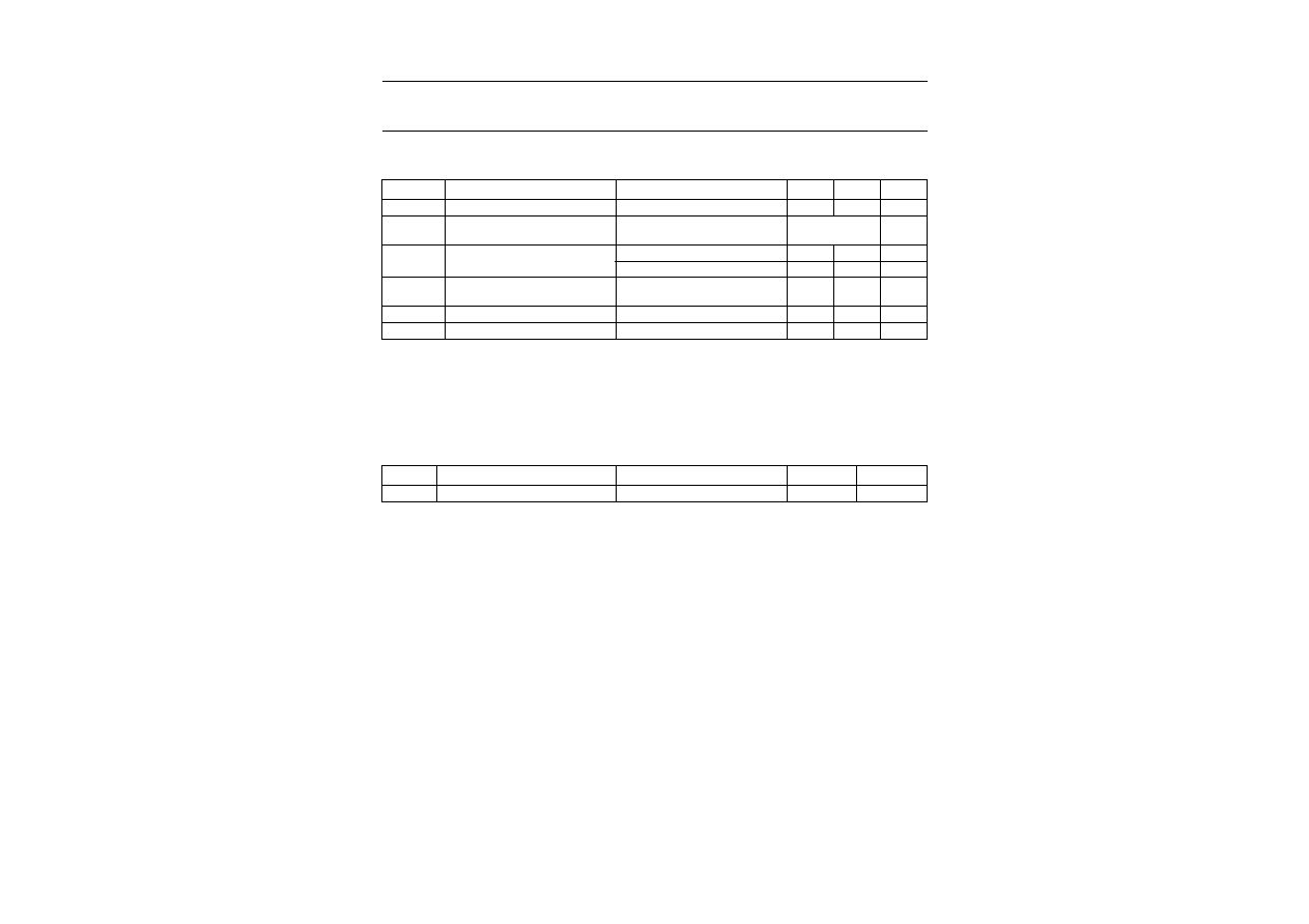
LIMITING VALUES
In accordance with the Absolute Maximum Rating System (IEC 134).
Notes
1. Device mounted on a ceramic substrate of 8
◊
10
◊
0.7 mm.
2. Device mounted on an FR4 printed circuit-board.
ELECTRICAL CHARACTERISTICS
Total series
T
j
= 25
∞
C unless otherwise specified.
SYMBOL
PARAMETER
CONDITIONS
MIN.
MAX.
UNIT
I
F
continuous forward current
-
200
mA
I
ZSM
non-repetitive peak reverse current
t
p
= 100
µ
s; square wave;
T
j
= 25
∞
C prior to surge
see Table
"Per type"
P
tot
total power dissipation
T
amb
= 25
∞
C; note 1
-
300
mW
T
amb
= 25
∞
C; note 2
-
250
mW
P
ZSM
non-repetitive peak reverse power
dissipation
t
p
= 100
µ
s; square wave;
T
j
= 25
∞
C prior to surge; see Fig.2
-
40
W
T
stg
storage temperature
-
65
+150
∞
C
T
j
junction temperature
-
150
∞
C
SYMBOL
PARAMETER
CONDITIONS
MAX.
UNIT
V
F
forward voltage
I
F
= 200 mA; see Fig.3
1.1
V

1999
May
17
4
Philips Semiconductors
Product specification
V
oltage regulator diodes
PMBZ5226B to PMBZ5257B
Per type
T
j
= 25
∞
C unless otherwise specified.
TYPE No.
WORKING
VOLTAGE
V
Z
(V)
(1)
at I
Ztest
DIFFERENTIAL
RESISTANCE
r
dif
(
)
at I
Z
= 0.25 mA
TEMP. COEFF.
S
Z
(%/K)
at I
Z
(2)
TEST
CURRENT
I
Ztest
(mA)
DIODE CAP.
C
d
(pF)
at f = 1 MHz;
at V
R
= 0 V
REVERSE CURRENT at
REVERSE VOLTAGE
NON-REPETITIVE PEAK
REVERSE CURRENT
I
ZSM
(A) at t
p
= 100
µ
s;
T
amb
= 25
∞
C
I
R
(
µ
A)
V
R
(V)
NOM.
MAX.
TYP.
MAX.
MAX.
MAX.
PMBZ5226B
3.3
1600
-
0.064
20
450
25
1.0
6.0
PMBZ5227B
3.6
1700
-
0.065
20
450
15
1.0
6.0
PMBZ5228B
3.9
1900
-
0.063
20
450
10
1.0
6.0
PMBZ5229B
4.3
2000
-
0.058
20
450
5
1.0
6.0
PMBZ5230B
4.7
2000
-
0.047
20
450
5
1.0
6.0
PMBZ5231B
5.1
2000
-
0.013
20
300
5
2.0
6.0
PMBZ5232B
5.6
1600
+0.023
20
300
5
3.0
6.0
PMBZ5233B
6.0
1600
+0.023
20
300
5
3.5
6.0
PMBZ5234B
6.2
1000
+0.039
20
200
5
4.0
6.0
PMBZ5235B
6.8
750
+0.040
20
200
3
5.0
6.0
PMBZ5236B
7.5
500
+0.047
20
150
3
6.0
4.0
PMBZ5237B
8.2
500
+0.052
20
150
3
6.5
4.0
PMBZ5238B
8.7
600
+0.053
20
150
3
6.5
3.5
PMBZ5239B
9.1
600
+0.055
20
150
3
7.0
3.0
PMBZ5240B
10
600
+0.055
20
90
3
8.0
3.0
PMBZ5241B
11
600
+0.058
20
85
2
8.4
2.5
PMBZ5242B
12
600
+0.062
20
85
1
9.1
2.5
PMBZ5243B
13
600
+0.065
9.5
80
0.5
9.9
2.5
PMBZ5244B
14
600
+0.067
9.0
80
0.1
10
2.0
PMBZ5245B
15
600
+0.073
8.5
75
0.1
11
2.0
PMBZ5246B
16
600
+0.073
7.8
75
0.1
12
1.5
PMBZ5247B
17
600
+0.073
7.4
75
0.1
13
1.5
PMBZ5248B
18
600
+0.078
7.0
70
0.1
14
1.5
PMBZ5249B
19
600
+0.078
6.6
70
0.1
14
1.5
PMBZ5250B
20
600
+0.080
6.2
60
0.1
15
1.5
PMBZ5251B
22
600
+0.080
5.6
60
0.1
17
1.25

1999
May
17
5
Philips Semiconductors
Product specification
V
oltage regulator diodes
PMBZ5226B to PMBZ5257B
Notes
1. V
Z
is measured with device at thermal equilibrium while mounted on a ceramic substrate of 8
◊
10
◊
0.7 mm.
2. For types PMBZ5226B to PMBZ5242B the I
Z
current is 7.5 mA; for PMBZ5243B and higher I
Z
= I
Ztest
. S
Z
values valid between 25
∞
C and 125
∞
C.
PMBZ5252B
24
600
+0.081
5.2
55
0.1
18
1.25
PMBZ5253B
25
600
+0.082
5.0
55
0.1
19
1.25
PMBZ5254B
27
600
+0.085
4.6
50
0.1
21
1.0
PMBZ5255B
28
600
+0.085
4.5
50
0.1
21
1.0
PMBZ5256B
30
600
+0.085
4.2
50
0.1
23
1.0
PMBZ5257B
33
700
+0.085
3.8
45
0.1
25
0.9
TYPE No.
WORKING
VOLTAGE
V
Z
(V)
(1)
at I
Ztest
DIFFERENTIAL
RESISTANCE
r
dif
(
)
at I
Z
= 0.25 mA
TEMP. COEFF.
S
Z
(%/K)
at I
Z
(2)
TEST
CURRENT
I
Ztest
(mA)
DIODE CAP.
C
d
(pF)
at f = 1 MHz;
at V
R
= 0 V
REVERSE CURRENT at
REVERSE VOLTAGE
NON-REPETITIVE PEAK
REVERSE CURRENT
I
ZSM
(A) at t
p
= 100
µ
s;
T
amb
= 25
∞
C
I
R
(
µ
A)
V
R
(V)
NOM.
MAX.
TYP.
MAX.
MAX.
MAX.