 | –≠–ª–µ–∫—Ç—Ä–æ–Ω–Ω—ã–π –∫–æ–º–ø–æ–Ω–µ–Ω—Ç: PMLL4151 | –°–∫–∞—á–∞—Ç—å:  PDF PDF  ZIP ZIP |

DATA SHEET
Product specification
Supersedes data of April 1996
1996 Sep 18
DISCRETE SEMICONDUCTORS
PMLL4150; PMLL4151;
PMLL4153
High-speed diodes
1/3 page (Datasheet)
M3D054

1996 Sep 18
2
Philips Semiconductors
Product specification
High-speed diodes
PMLL4150; PMLL4151; PMLL4153
FEATURES
∑
Small hermetically sealed glass
SMD package
∑
High switching speed: max. 4 ns
∑
General application
∑
Continuous reverse voltage:
max. 50 V
∑
Repetitive peak reverse voltage:
max. 75 V
∑
Repetitive peak forward current:
max. 600 mA and 450 mA
respectively.
APPLICATIONS
∑
High-speed switching
∑
The PMLL4150 is primarily
intended for general purpose use in
computer and industrial
applications.
∑
The PMLL4151 and PMLL4153 are
intended for military and industrial
applications.
DESCRIPTION
The PMLL4150, PMLL4151, PMLL4153 are high-speed switching diodes
fabricated in planar technology, and encapsulated in small hermetically sealed
glass SOD80C SMD packages.
Fig.1 Simplified outline (SOD80C) and symbol.
Cathode indicated by black band.
handbook, 4 columns
MAM061
k
a

1996 Sep 18
3
Philips Semiconductors
Product specification
High-speed diodes
PMLL4150; PMLL4151; PMLL4153
LIMITING VALUES
In accordance with the Absolute Maximum Rating System (IEC 134).
Note
1. Device mounted on an FR4 printed-circuit board.
SYMBOL
PARAMETER
CONDITIONS
MIN.
MAX.
UNIT
V
RRM
repetitive peak reverse voltage
PMLL4151
-
75
V
PMLL4153
-
75
V
V
R
continuous reverse voltage
-
50
V
I
F
continuous forward current
see Fig.2; note 1
PMLL4150
-
300
mA
PMLL4151
-
200
mA
PMLL4153
-
200
mA
I
FRM
repetitive peak forward current
PMLL4150
-
600
mA
PMLL4151
-
450
mA
PMLL4153
-
450
mA
I
FSM
non-repetitive peak forward current
square wave; T
j
= 25
∞
C prior to
surge; see Fig.4
t = 1
µ
s
-
4
A
t = 1 ms
-
1
A
t = 1 s
-
0.5
A
P
tot
total power dissipation
T
amb
= 25
∞
C; note 1
-
500
mW
T
stg
storage temperature
-
65
+200
∞
C
T
j
junction temperature
-
200
∞
C

1996 Sep 18
4
Philips Semiconductors
Product specification
High-speed diodes
PMLL4150; PMLL4151; PMLL4153
ELECTRICAL CHARACTERISTICS
T
j
= 25
∞
C; unless otherwise specified.
SYMBOL
PARAMETER
CONDITIONS
MIN.
MAX.
UNIT
V
F
forward voltage
see Fig.3
PMLL4150
I
F
= 1 mA
540
620
mV
I
F
= 10 mA
660
740
mV
I
F
= 50 mA
760
860
mV
I
F
= 100 mA
820
920
mV
I
F
= 200 mA
870
1000
mV
PMLL4151
I
F
= 50 mA
-
1000
mV
PMLL4153
I
F
= 0.1 mA
490
550
mV
I
F
= 0.25 mA
530
590
mV
I
F
= 1 mA
590
670
mV
I
F
= 2 mA
620
700
mV
I
F
= 10 mA
700
810
mV
I
F
= 50 mA
740
880
mV
I
R
reverse current
V
R
= 50 V; see Fig.5
PMLL4150
-
0.1
µ
A
PMLL4151
-
0.05
µ
A
PMLL4153
-
0.05
µ
A
I
R
reverse current
V
R
= 50 V; T
j
= 150
∞
C; see Fig.5
PMLL4150
-
100
µ
A
PMLL4151
-
50
µ
A
PMLL4153
-
50
µ
A
C
d
diode capacitance
f = 1 MHz; V
R
= 0; see Fig.6
PMLL4150
-
2.5
pF
PMLL4151
-
2
pF
PMLL4153
2
pF

1996 Sep 18
5
Philips Semiconductors
Product specification
High-speed diodes
PMLL4150; PMLL4151; PMLL4153
THERMAL CHARACTERISTICS
Note
1. Device mounted on an FR4 printed-circuit board.
t
rr
reverse recovery time
when switched from I
F
= 10 mA to
I
R
= 1 mA; R
L
= 100
; measured at
I
R
= 0.1 mA; see Fig.7
PMLL4150
-
6
ns
when switched from I
F
= 10 mA to
200 mA to I
R
= 10 mA to 200 mA;
R
L
= 100
; measured at I
R
= 0.1
◊
I
F
;
see Fig.7
-
4
ns
when switched from I
F
= 200 mA to
400 mA to I
R
= 200 mA to 400 mA;
R
L
= 100
; measured at I
R
= 0.1
◊
I
F
;
see Fig.7
-
6
ns
t
rr
reverse recovery time
when switched from I
F
= 10 mA to
I
R
= 10 mA; R
L
= 100
; measured at
I
R
= 1 mA; see Fig.7
PMLL4151
-
4
ns
when switched from I
F
= 10 mA to
I
R
= 60 mA; R
L
= 100
; measured at
I
R
= 1 mA; see Fig.7
-
2
ns
t
rr
reverse recovery time
when switched from I
F
= 10 mA to
I
R
= 10 mA; R
L
= 100
; measured at
I
R
= 1 mA; see Fig.7
PMLL4153
-
4
ns
when switched from I
F
= 10 mA to
I
R
= 60 mA; R
L
= 100
; measured at
I
R
= 1 mA; see Fig.7
-
2
ns
t
fr
forward recovery time
when switched to I
F
= 200 mA; t
r
= 0.4 ns;
measured at V
F
= 1 V; see Fig.8
-
10
ns
SYMBOL
PARAMETER
CONDITIONS
VALUE
UNIT
R
th j-tp
thermal resistance from junction to tie-point
300
K/W
R
th j-a
thermal resistance from junction to ambient
note 1
350
K/W
SYMBOL
PARAMETER
CONDITIONS
MIN.
MAX.
UNIT

1996 Sep 18
6
Philips Semiconductors
Product specification
High-speed diodes
PMLL4150; PMLL4151; PMLL4153
GRAPHICAL DATA
Device mounted on an FR4 printed-circuit board.
(1) PMLL4150.
(2) PMLL4151; PMLL4153.
Fig.0
Maximum permissible continuous forward
current as a function of ambient
temperature.
handbook, halfpage
0
100
200
400
300
200
0
100
MBG456
Tamb (
o
C)
IF
(mA)
(1)
(2)
Fig.3
Forward current as a function of forward
voltage.
handbook, halfpage
0
1
2
600
0
200
400
MBG464
VF (V)
IF
(mA)
(1)
(2)
(3)
(1) T
j
= 175
∞
C; typical values.
(2) T
j
= 25
∞
C; typical values.
(3) T
j
= 25
∞
C; maximum values.
Fig.4
Maximum permissible non-repetitive peak forward current as a function of pulse duration.
Based on square wave currents.
T
j
= 25
∞
C prior to surge.
handbook, full pagewidth
MBG704
10
tp (
µ
s)
1
IFSM
(A)
10
2
10
-
1
10
4
10
2
10
3
10
1

1996 Sep 18
7
Philips Semiconductors
Product specification
High-speed diodes
PMLL4150; PMLL4151; PMLL4153
Fig.5
Reverse current as a function of junction
temperature.
handbook, halfpage
0
100
Tj (
o
C)
200
10
3
10
2
10
-
1
10
-
2
10
(1)
(2)
1
IR
(
µ
A)
MGD006
(3)
(1) V
R
= 75 V; maximum values.
(2) V
R
= 75 V; typical values.
(3) V
R
= 20 V; typical values.
Fig.6
Diode capacitance as a function of reverse
voltage; typical values.
f = 1 MHz; T
j
= 25
∞
C.
handbook, halfpage
0
10
20
1.2
1.0
0.6
0.4
0.8
MGD004
VR (V)
Cd
(pF)
1996 Sep 18
8
Philips Semiconductors
Product specification
High-speed diodes
PMLL4150; PMLL4151; PMLL4153
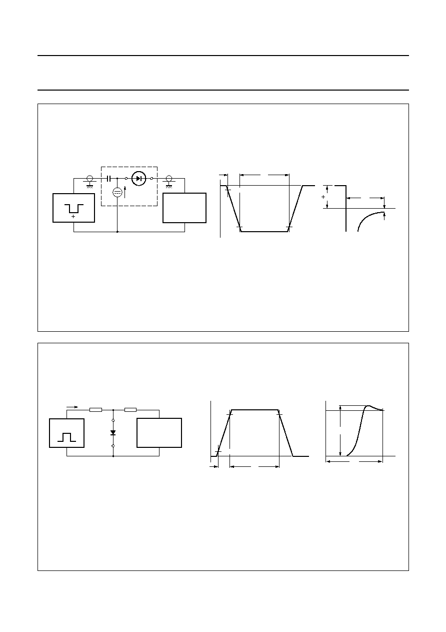
Fig.7 Reverse recovery voltage test circuit and waveforms.
handbook, full pagewidth
t rr
(1)
I F
t
output signal
t r
t
t p
10%
90%
VR
input signal
V = V I x R
R
F
S
R = 50
S
IF
D.U.T.
R = 50
i
SAMPLING
OSCILLOSCOPE
MGA881
(1) The value of I
R
is dependent on product type.
Fig.8 Forward recovery time test circuit and waveforms.
Input signal: forward pulse rise time t
r
= 0.4 ns; forward pulse duration t
p
= 100 ns; duty factor
= 0.01.
t r
t
t p
10%
90%
I
input
signal
R = 50
S
I
R = 50
i
OSCILLOSCOPE
1 k
450
D.U.T.
MBH181
Vfr
tfr
t
output
signal
VF
(V)
1.0

1996 Sep 18
9
Philips Semiconductors
Product specification
High-speed diodes
PMLL4150; PMLL4151; PMLL4153
PACKAGE OUTLINE
DEFINITIONS
LIFE SUPPORT APPLICATIONS
These products are not designed for use in life support appliances, devices, or systems where malfunction of these
products can reasonably be expected to result in personal injury. Philips customers using or selling these products for
use in such applications do so at their own risk and agree to fully indemnify Philips for any damages resulting from such
improper use or sale.
Data Sheet Status
Objective specification
This data sheet contains target or goal specifications for product development.
Preliminary specification
This data sheet contains preliminary data; supplementary data may be published later.
Product specification
This data sheet contains final product specifications.
Limiting values
Limiting values given are in accordance with the Absolute Maximum Rating System (IEC 134). Stress above one or
more of the limiting values may cause permanent damage to the device. These are stress ratings only and operation
of the device at these or at any other conditions above those given in the Characteristics sections of the specification
is not implied. Exposure to limiting values for extended periods may affect device reliability.
Application information
Where application information is given, it is advisory and does not form part of the specification.
Fig.9 SOD80C.
Dimensions in mm.
handbook, full pagewidth
MBA390 - 2
1.60
1.45
3.7
3.3
0.3
0.3
O