1996 Apr 26
2
Philips Semiconductors
Product specification
Voltage regulator diodes
PMLL5225B to PMLL5267B
FEATURES
∑
Total power dissipation:
max. 500 mW
∑
Tolerance series:
±
5%
∑
Working voltage range:
nom. 3.0 to 75 V
∑
Non-repetitive peak reverse power
dissipation: max. 40 W.
APPLICATIONS
∑
Low-power voltage stabilizers or
voltage references.
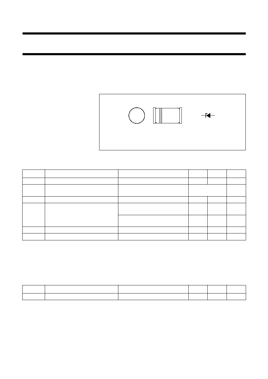
DESCRIPTION
Low-power voltage regulator diodes in small hermetically sealed glass
SOD80C SMD packages. The series consists of 43 types with nominal working
voltages from 3.0 to 75 V.
Fig.1 Simplified outline (SOD80C) and symbol.
The cathode is indicated by a yellow band.
handbook, 4 columns
MAM215
k
a
LIMITING VALUES
In accordance with the Absolute Maximum Rating System (IEC 134).
Note
1. If flanges are kept at T
flange
75
∞
C.
ELECTRICAL CHARACTERISTICS
Total series
T
j
= 25
∞
C; unless otherwise specified.
SYMBOL
PARAMETER
CONDITIONS
MIN.
MAX.
UNIT
I
F
continuous forward current
-
250
mA
I
ZSM
non-repetitive peak reverse current
t
p
= 100
µ
s; square wave;
T
j
= 25
∞
C prior to surge
see Table
"Per type"
P
tot
total power dissipation
T
amb
= 25
∞
C; note 1
-
500
mW
P
ZSM
non-repetitive peak reverse power
dissipation
t
p
= 100
µ
s; square wave;
T
j
= 25
∞
C prior to surge; see Fig.3
-
40
W
t
p
= 8.3 ms; square wave;
T
j
55
∞
C prior to surge
-
10
W
T
stg
storage temperature
-
65
+200
∞
C
T
j
junction temperature
-
65
+200
∞
C
SYMBOL
PARAMETER
CONDITIONS
MIN.
MAX.
UNIT
V
F
forward voltage
I
F
= 200 mA; see Fig.4
-
1.1
V

1996
Apr
26
4
Philips Semiconductors
Product specification
V
oltage regulator diodes
PMLL5225B to PMLL5267B
Notes
1. V
Z
is measured with device at thermal equilibrium while held in clips at 10 mm from body in still air at 25
∞
C.
2. For types PMLL5225B to PMLL5242B the I
Z
current is 7.5 mA; for PMLL5243B and higher I
Z
= I
Ztest
. S
Z
values valid between 25
∞
C and 125
∞
C.
PMLL5251B
22
600
+0.087
5.6
60
0.1
17.0
1.25
PMLL5252B
24
600
+0.088
5.2
55
0.1
18.0
1.25
PMLL5253B
25
600
+0.089
5.0
55
0.1
19.0
1.25
PMLL5254B
27
600
+0.090
4.6
50
0.1
21.0
1.0
PMLL5255B
28
600
+0.091
4.5
50
0.1
21.0
1.0
PMLL5256B
30
600
+0.091
4.2
50
0.1
23.0
1.0
PMLL5257B
33
700
+0.092
3.8
45
0.1
25.0
0.9
PMLL5258B
36
700
+0.093
3.4
45
0.1
27.0
0.8
PMLL5259B
39
800
+0.094
3.2
45
0.1
30.0
0.7
PMLL5260B
43
900
+0.095
3.0
40
0.1
33.0
0.6
PMLL5261B
47
1000
+0.095
2.7
40
0.1
36.0
0.5
PMLL5262B
51
1100
+0.096
2.5
40
0.1
39.0
0.4
PMLL5263B
56
1300
+0.096
2.2
40
0.1
43.0
0.3
PMLL5264B
60
1400
+0.097
2.1
40
0.1
46.0
0.3
PMLL5265B
62
1400
+0.097
2.0
35
0.1
47.0
0.3
PMLL5266B
68
1600
+0.097
1.8
35
0.1
52.0
0.25
PMLL5267B
75
1700
+0.098
1.7
35
0.1
56.0
0.2
TYPE No.
WORKING
VOLTAGE
V
Z
(V)
(1)
at I
Ztest
DIFFERENTIAL
RESISTANCE
r
dif
(
)
at I
Ztest
TEMP. COEFF.
S
Z
(%/K)
at I
Z
(2)
TEST
CURRENT
I
Ztest
(mA)
DIODE CAP.
C
d
(pF)
at f = 1 MHz;
at V
R
= 0 V
REVERSE CURRENT
at REVERSE
VOLTAGE
NON-REPETITIVE PEAK
REVERSE CURRENT
I
ZSM
(A)
at t
p
= 100
µ
s; T
amb
= 25
∞
C
I
R
(
µ
A)
V
R
(V)
NOM.
MAX.
MAX.
MAX.
MAX.
MAX.

1996 Apr 26
5
Philips Semiconductors
Product specification
Voltage regulator diodes
PMLL5225B to PMLL5267B
THERMAL CHARACTERISTICS
Note
1. Device mounted on a printed circuit-board without metallization pad.
SYMBOL
PARAMETER
CONDITIONS
VALUE
UNIT
R
th j-tp
thermal resistance from junction to tie-point lead length 10 mm
300
K/W
R
th j-a
thermal resistance from junction to ambient lead length max.; see Fig.2 and note 1
380
K/W

