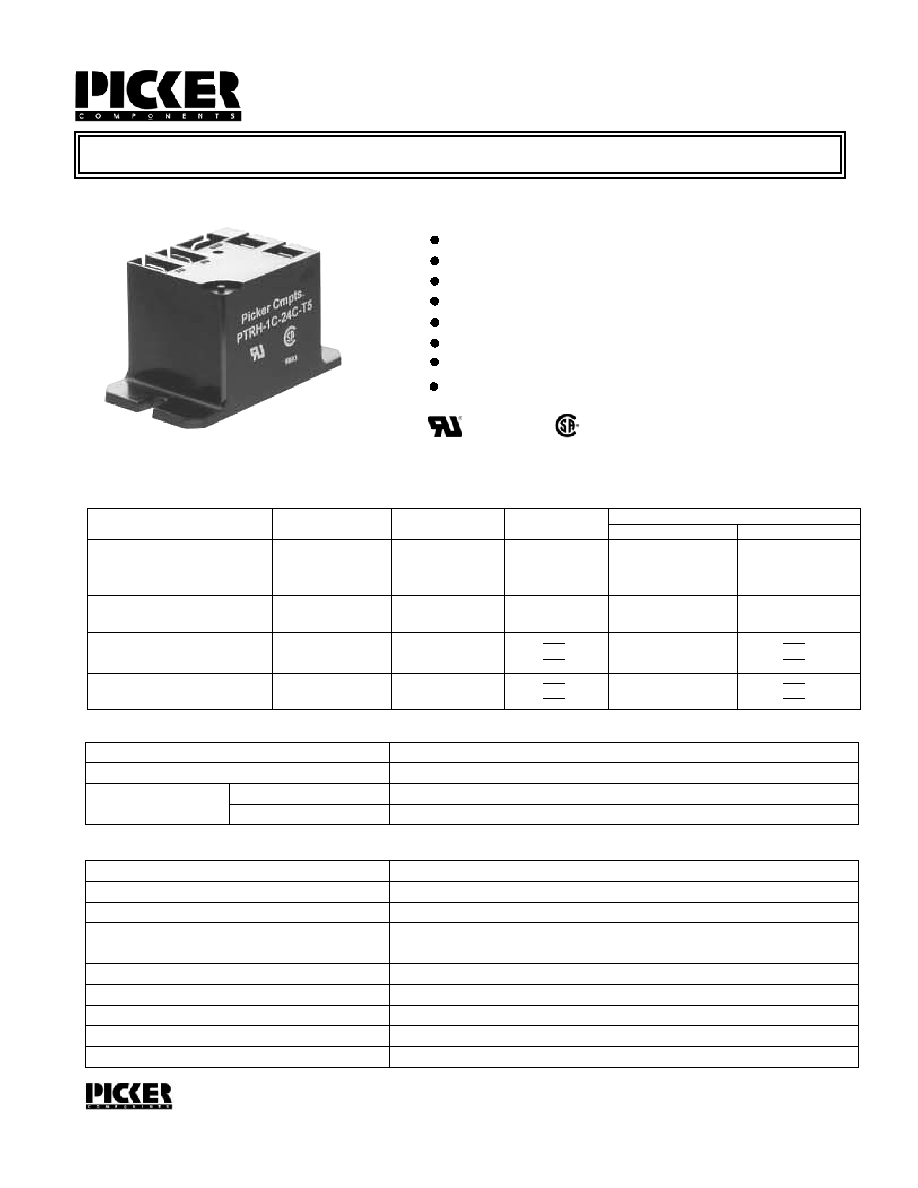
30 AMP Panel Mount or PCB Power Relay
FEATURES
Panel or PC mount with QC terminals for the load
Up to 30 amp switching capacity
Gold flashed contacts available
Up to 2 horsepower rating
UL Class B insulation standard
UL Class F insulation available
PTRH-T
UL 873 spacing standard
Load Type
General Purpose
Resistive ( 100,000 cycles)
Motor ( 30,000 cycles )
LRA/FLA
Voltage
120 VAC
250 VAC
30 VDC
250 VAC
120 VAC
250 VAC
120 VAC
1 Form A
30 A
30 A
30 A
2 HP
1 HP
80 A/30 A
96 A/30 A
1 Form B
20 A
20 A
20 A
1 Form C (SPDT)
NO
NC
30 A
30 A
30 A
2 HP
1 HP
96 A/30 A
UL/CSA RATINGS
CONTACT DATA
Material
Initial Contact Resistance
Service Life
Mechanical
Electrical
AgCdO (Silver Cadmium Oxide), AgCdO+Au (Silver Cadmium Oxide with Gold flash)
50 milliohms max @ 0.1A, 6VDC
1 X 10
7
1 X 10
5
CHARACTERISTICS
Operate Time
15 ms. typical
Release Time
Insulation Resistance
10 ms. typical
1,000 megohms min, at 500VDC, 50%RH
Dielectric Strength
1500 Vrms, 1 min. between open contacts
1500 Vrms, 1 min. between coil and contacts
Shock Resistance
10 g, 11ms, functional; 100 g, destructive
Vibration Resistance
DA 1.5mm, 10-55 Hz
Power Consumption
0.9W, approx.
Ambient Temperature Range
-55 degrees C to 85 degrees C operating for class B, -40 to 130 degrees C storage
Weight
30 grams approx.
120 VAC
250 VAC
30 A
30 A
80 A/30 A
30 A
30 A
Operations
Operations
Sales: Call Toll Free (888)997-3933 Fax (818) 342-5296 email: pickerwest@sbcglobal.net URL: pickercomponents.com
3220 Commander Drive, Suite 102, Carrollton, Texas 75006
File # E93379
Certificate # LR 109231
Epoxy sealed, immersion cleanable
(SPST-NO)
(SPST-NC)
(locked rotor amps/full load amps)
PTRH-T Rev D 3-25-04
20 A
20 A
20 A
20 A
20 A
20 A
20 A
PAGE 1
PTRH-T
PTRH-T
ORDERING INFORMATION
Example:
PTRH
Model
-12
Coil Voltage
-1C
Contact Form
1A, 1B, or 1C
S
Configueration
Nil: Open Frame; C: Dust Cover S: Sealed plastic case
COIL DATA
Coil Voltage
5
6
9
12
24
48
110
Resistance
ohms + 10%
Must Operate
Voltage Max.
(VDC)
Must Release
Voltage Min.
(VDC)
Continuous
Voltage Max.
(VDC)
27
40
97
155
660
2560
10330
3.75
4.50
6.75
9.00
18.00
36.00
82.50
0.5
0.6
0.9
1.2
2.4
4.8
11.0
5.5
6.6
9.9
13.2
26.4
52.8
121.0
_
Contact Material
Nil: AgCdO; T: AgSnO; G: AgCdO+Au
G
Insulation Material
Nil: UL Class B; F: UL Class F
F
Mounting Type
T2: Form 1A PCB & QC, T3: Form 1C PCB & QC, T4: 1A Panel all QC, T5: 1C Panel all QC
-T5
Sales: Call Toll Free (888) 997-3933 Fax (818) 342-5296 email: pickerwest@sbcglobal.net URL: pickercomponents.com
3220 Commander Drive, Suite 102, Carrollton, Texas 75006
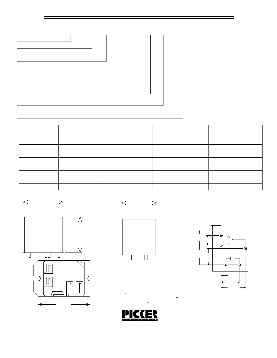
.250 Ref.
(6.35)
.440
(11.2) .300
(7.6)
.600
(15.2) .500
.150
(3.81)
.550
(13.97)
.700
(17.78)
(12.7)
NO
NC
Pin Layout
Bottom View
(32.2)
1.27
1.10
(28.0)
(27.5)
1.08
Overall Dimensions
Inches (millimeters)
Including Schematic
max
max
max
COM
1.71
(43.5)
Notes:
Breakable nib may be removed after flux removal.
PC mount has .250 male QC terminals for load.
Panel mount has .250 male QC terminals for the load
and .187 male QC terminals for the coil.
PAGE 2
Note: Custom coil voltages within the ranges shown are available on special order.
Tolerances + .010 unless otherwise noted
Holes for Coil term. .043
Holes for load term. .081 + .005 Dia. (2.06 + .13)
+ .003 Dia. (1.09 + .08)