 | –≠–ª–µ–∫—Ç—Ä–æ–Ω–Ω—ã–π –∫–æ–º–ø–æ–Ω–µ–Ω—Ç: PS21869 | –°–∫–∞—á–∞—Ç—å:  PDF PDF  ZIP ZIP |

Powerex, Inc., 200 E. Hillis Street, Youngwood, Pennsylvania 15697-1800 (724) 925-7272
IntellimodTM Module
Dual-In-Line Intelligent
Power Module
50 Amperes/600 Volts
PS21869
99
Description:
DIP-IPMs are intelligent power
modules that integrate power
devices, drivers, and protection
circuitry in an ultra compact
dual-in-line transfer-mold package
for use in driving small three
phase motors. Use of 5th
generation IGBTs, DIP packaging,
and application specific HVICs
allow the designer to reduce
inverter size and overall design
time.
Features:
£
Compact Packages
£
Single Power Supply
£
Integrated HVICs
£
Direct Connection to CPU
Applications:
£
Washing Machines
£
Refrigerators
£
Air Conditioners
£
Small Servo Motors
£
Small Motor Control
Ordering Information:
PS21869 is a 600V, 50 Ampere
DIP Intelligent Power Module.
Dimensions
Inches
Millimeters
A 3.11±0.02
79.0±0.5
B 1.22±0.02
31.0±0.5
C 0.28±0.02
7.0±0.5
D 2.64±0.01
67.0±0.3
E 0.53±0.02
13.4±0.5
F 0.84±0.02
21.4±0.5
G 1.37±0.02
34.9±0.5
H 0.15±0.01
3.8±0.2
J 0.11±0.01
2.8±0.3
K 0.39±0.01
10.0±0.3
L 0.79±0.01
20.0±0.3
M 0.50±0.04
12.8±1.0
N 2.98 75.6
Dimensions
Inches
Millimeters
P 0.04
1.0
Q 0.18±0.01 Dia. 4.5±0.2 Dia.
R 0.15
3.8
S Min.
1.0 Min.
T 0.02 Min.
0.7 Min.
U 0.1 2.5
V 0.03±0.01
0.8±0.2
W 0.02 0.7
X 0.45±0.02
11.5±0.5
Y 0.18 4.5
Z 0.12 3.1
AA 0.02 0.6
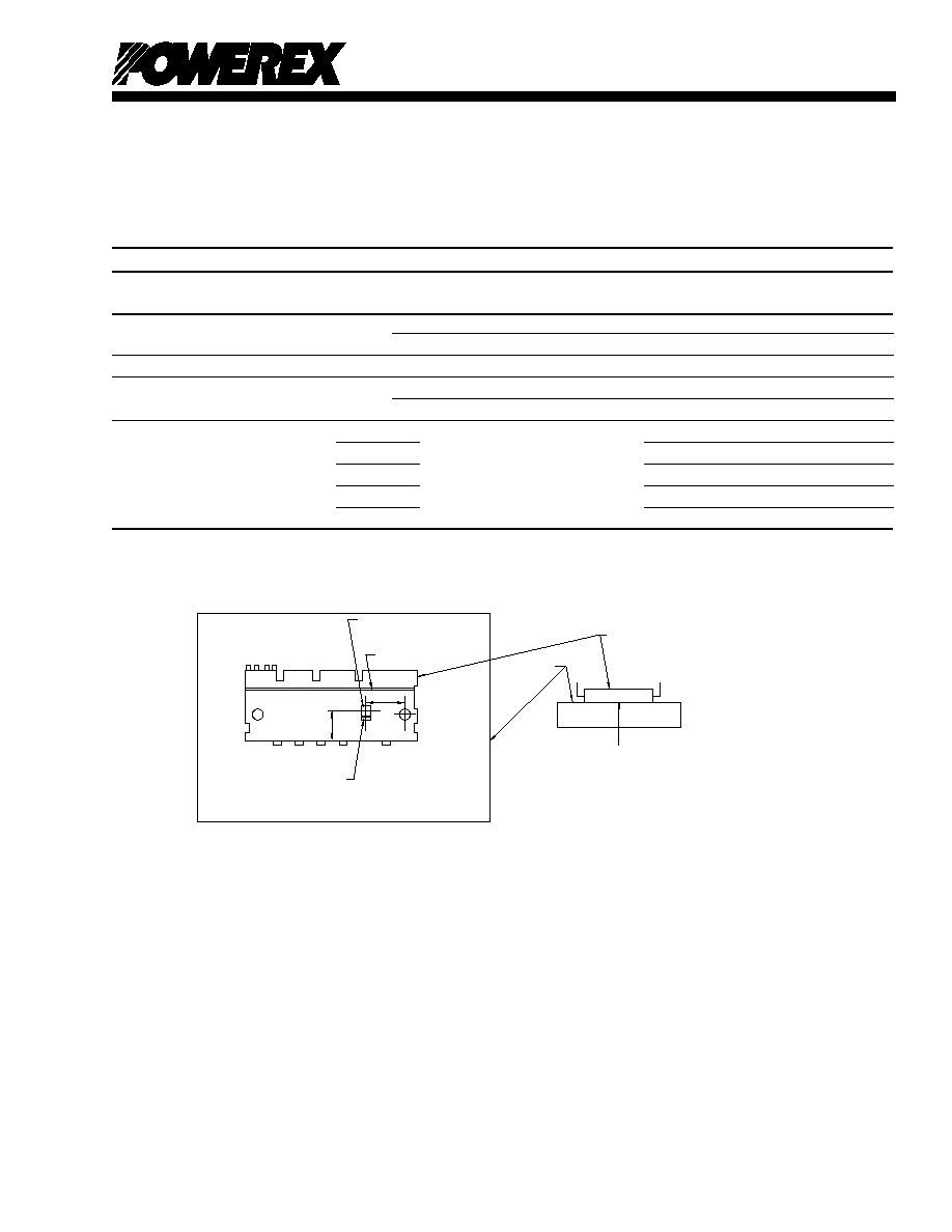
Outline Drawing and Circuit Diagram
HEATSINK
SIDE
S
U
U
V
W
V
T
Q (2 PLACES)
N
LABEL
POWER SIDE
DETAIL "A"
DETAIL
"A"
DETAIL "A"
DETAIL "B"
DETAIL "B"
DETAIL "C"
DETAIL "C"
CONTROL SIDE
M
L
K
K
K
J
X
H
G
F
E
AA
C
D
B
Y
AA
Z
A
P
1
2
3
4
5 6
7 8
9 10 11
27
28
30
31
33
35
36
37
38
39
40
41
34
32
29
12 13
14 15 16 17 18 19 20
21
22
23
24
25
26
6 V
P1
5 V
P
3 V
UFB
2 V
P1
26 N
U
N
19
24 V
23 U
22 P
21 W
N
25 W
20 V
N
28 NC
27 NC
33 NC
31 NC
30 NC
29 NC
32 NC
35 NC
34 NC
40 NC
38 NC
37 NC
36 NC
39 NC
41 NC
7 V
VFB
9 W
P
11 V
PC
10 V
P1
12 V
WFB
1 U
P
4 V
UFS
8 V
VFS
16 C
IN
15 V
NC
17 C
FO
18 F
O
13 V
WFS
14 V
N1
TERMINAL CODE
R

PS21869
IntellimodTM Module
Dual-In-Line Intelligent Power Module
50 Amperes/600 Volts
100
Powerex, Inc., 200 E. Hillis Street, Youngwood, Pennsylvania 15697-1800 (724) 925-7272
101
PS21869
IntellimodTM Module
Dual-In-Line Intelligent Power Module
50 Amperes/600 Volts
Powerex, Inc., 200 E. Hillis Street, Youngwood, Pennsylvania 15697-1800 (724) 925-7272
Absolute Maximum Ratings, T
j
= 25∞C unless otherwise specified
Characteristics
Symbol
PS21869
Units
Power Device Junction Temperature*
T
j
-20 to 125
∞C
Module Case Operation Temperature (See T
f
Measurement Point Illustration)
T
f
-20 to 100
∞C
Storage Temperature
T
stg
-40 to 125
∞C
Mounting Torque, M4 Mounting Screws
--
13
in-lb
Module Weight (Typical)
--
65
Grams
Self-protection Supply Voltage Limit (Short Circuit Protection Capability)**
V
CC(prot.)
400
Volts
Isolation Voltage, AC 1 minute, 60Hz Sinusoidal, Connection Pins to Heatsink Plate
V
ISO
2500
Volts
*The maximum junction temperature rating of the power chips integrated within the DIP-IPM is 150∞C (@T
f
100∞C). However, to ensure safe operation of the DIP-IPM,
the average junction temperature should be limited to T
j(avg)
125∞C (@T
f
100∞C).
**V
D
= 13.5 ~ 16.5V, Inverter Part, T
j
= 125∞C, Non-repetitive, Less than 2µs
IGBT Inverter Sector
Collector-Emitter Voltage (T
f
= 25∞C)
V
CES
600
Volts
Collector Current (T
f
= 25∞C)
±I
C
50
Amperes
Peak Collector Current (T
f
= 25∞C, <1ms)
±I
CP
100
Amperes
Supply Voltage (Applied between P - N)
V
CC
450
Volts
Supply Voltage, Surge (Applied between P - N)
V
CC(surge)
500
Volts
Collector Dissipation (T
f
= 25∞C, per 1 Chip)
P
C
70.4
Watts
Control Sector
Supply Voltage (Applied between V
P1
-V
PC
, V
N1
-V
NC
)
V
D
20
Volts
Supply Voltage (Applied between V
UFB
-V
UFS
,
V
VFB
-V
VFS
, V
WFB
-V
WFS
)
V
DB
20
Volts
Input Voltage (Applied between U
P
, V
P
, W
P
-V
PC
, U
N
, V
N
, W
N
-V
NC
)
V
IN
-0.5 ~ V
D
+0.5
Volts
Fault Output Supply Voltage (Applied between F
O
-V
NC
)
V
FO
-0.5 ~ V
D
+0.5
Volts
Fault Output Current (Sink Current at F
O
Terminal)
I
FO
1
mA
Current Sensing Input Voltage (Applied between C
IN
-V
NC
)
V
SC
-0.5 ~ V
D
+0.5
Volts
PS21869
IntellimodTM Module
Dual-In-Line Intelligent Power Module
50 Amperes/600 Volts
100
Powerex, Inc., 200 E. Hillis Street, Youngwood, Pennsylvania 15697-1800 (724) 925-7272
101
PS21869
IntellimodTM Module
Dual-In-Line Intelligent Power Module
50 Amperes/600 Volts
Powerex, Inc., 200 E. Hillis Street, Youngwood, Pennsylvania 15697-1800 (724) 925-7272
Electrical and Mechanical Characteristics, T
j
= 25∞C unless otherwise specified
Characteristics Symbol Test Conditions Min. Typ. Max. Units
IGBT Inverter Sector
Collector-Emitter Cutoff Current I
CES
V
CE
= V
CES
, T
j
= 25∞C -- -- 1.0 mA
V
CE
= V
CES
, T
j
= 125∞C -- -- 10 mA
Diode Forward Voltage V
EC
T
j
= 25∞C, -I
C
= 50A, V
IN
= 5V -- 1.70 2.20 Volts
Collector-Emitter Saturation Voltage V
CE(sat)
I
C
= 50A, T
j
= 25∞C, V
D
= V
DB
= 15V, V
IN
= 0V -- 1.50 2.00 Volts
I
C
= 50A, T
j
= 125∞C, V
D
= V
DB
= 15V, V
IN
= 0V -- 1.60 2.10 Volts
Inductive Load Switching Times t
on
0.70 1.30 1.90 µs
t
rr
V
CC
= 300V, V
D
= V
DB
= 15V, -- 0.30 -- µs
t
C(on)
I
C
= 50A, T
j
= 125∞C, V
IN
= 5 0V, -- 0.40 0.60 µs
t
off
Inductive Load (Upper-Lower Arm) -- 2.00 2.60 µs
t
C(off)
-- 0.65 0.90 µs
T
f
Measurement Point
FWDi CHIP
POWER TERMINALS
P
U
13.5mm
18mm
GROOVE
CONTROL TERMINALS
IGBT CHIP
V
W
N
Al BOARD
DIP-IPM
TEMPERATURE
MEASUREMENT POINT
(INSIDE THE Al BOARD)
TEMPERATURE
MEASUREMENT POINT
(INSIDE THE Al BOARD)

PS21869
IntellimodTM Module
Dual-In-Line Intelligent Power Module
50 Amperes/600 Volts
102
Powerex, Inc., 200 E. Hillis Street, Youngwood, Pennsylvania 15697-1800 (724) 925-7272
103
PS21869
IntellimodTM Module
Dual-In-Line Intelligent Power Module
50 Amperes/600 Volts
Powerex, Inc., 200 E. Hillis Street, Youngwood, Pennsylvania 15697-1800 (724) 925-7272
Electrical and Mechanical Characteristics, T
j
= 25∞C unless otherwise specified
Characteristics Symbol Test Conditions Min. Typ. Max. Units
Control Sector
Supply Voltage V
D
Applied between V
P1
-V
PC
, V
N1
-V
NC
13.5 15.0 16.5 Volts
V
DB
Applied between V
UFB
-V
UFS
, 13.0 15.0 18.5 Volts
V
VFB
-V
VFS
, V
WFB
-V
WFS
Circuit Current I
D
V
D
= V
DB
= 15V, V
IN
= 5V, -- -- 5.00 mA
Total of V
P1
-V
PC
, V
N1
-V
NC
V
D
= V
DB
= 15V, V
IN
= 0V, -- -- 7.00 mA
Total of V
P1
-V
PC
, V
N1
-V
NC
V
D
= V
DB
= 15V, V
IN
= 5V, -- -- 0.40 mA
V
UFB
-V
UFS
, V
VFB
-V
VFS
, V
WFB
-V
WFS
V
D
= V
DB
= 15V, V
IN
= 0V, -- -- 0.55 mA
V
UFB
-V
UFS
, V
VFB
-V
VFS
, V
WFB
-V
WFS
Fault Output Voltage V
FOH
V
SC
= 0V, F
O
Circuit: 10k to 5V Pull-up 4.9 -- -- Volts
V
FOL
V
SC
= 1V, I
FO
= 1mA -- -- 0.95 Volts
Input Current I
IN
V
IN
= 5V 1.00 1.50 2.00 mA
Short-Circuit Trip Level* V
SC(ref)
T
j
= 25∞C, V
D
= 15V 0.43 0.48 0.53 Volts
Supply Circuit Undervoltage UV
DBt
Trip Level, T
j
125∞C 10.0 -- 12.0 Volts
Protection UV
DBr
Reset Level, T
j
125∞C 10.5 -- 12.5 Volts
UV
Dt
Trip Level, T
j
125∞C 10.3 -- 12.5 Volts
UV
Dr
Reset Level, T
j
125∞C 10.8 -- 13.0 Volts
Fault Output Pulse Width** t
FO
C
FO
= 22nF 1.0 1.8 -- ms
ON Threshold Voltage V
th(on)
Applied between U
P
, V
P
, W
P
-V
PC,
2.1 2.3 2.6 Volts
OFF Threshold Voltage V
th(off)
U
N
, V
N
, W
N
-V
NC
0.8 1.4 2.1 Volts
Thermal Characteristics
Characteristic Symbol Condition Min. Typ. Max. Units
Junction to Fin R
th(j-f)Q
IGBT Part (Per 1/6 Module) -- -- 1.42 ∞C/Watt
Thermal Resistance R
th(j-f)D
FWDi Part (Per 1/6 Module) -- -- 2.00 ∞C/Watt
Recommended Conditions for Use
Characteristic Symbol Condition Min. Typ. Max. Units
Supply Voltage V
CC
Applied between P-N Terminals 0 300 400 Volts
Control Supply Voltage V
D
Applied between V
P1
-V
PC
, V
N1
-V
NC
13.5 15.0 16.5 Volts
V
DB
Applied between V
UFB
-V
UFS
,
13.0 15.0 18.5 Volts
V
VFB
-V
VFS
, V
WFB
-V
WFS
Control Supply Variation
V
D
, V
DB
-1 -- 1 V/µs
PWM Input Frequency f
PWM
T
f
100∞C, T
j
125∞C -- -- 20 kHz
* Short-Circuit protection is functioning only at the lower arms. Please select the value of the external shunt resistor such that the SC trip level is less than 85A.
**Fault signal is asserted when the lower arm short circuit or control supply under-voltage protective functions operate. The fault output pulse-width t
FO
depends on the capacitance value
of C
FO
according to the following approximate equation: C
FO
= (12.2 x 10
-6
) x t
FO
{F} .
PS21869
IntellimodTM Module
Dual-In-Line Intelligent Power Module
50 Amperes/600 Volts
102
Powerex, Inc., 200 E. Hillis Street, Youngwood, Pennsylvania 15697-1800 (724) 925-7272
103
PS21869
IntellimodTM Module
Dual-In-Line Intelligent Power Module
50 Amperes/600 Volts
Powerex, Inc., 200 E. Hillis Street, Youngwood, Pennsylvania 15697-1800 (724) 925-7272
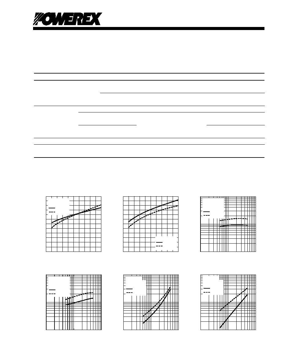
V
CC
= 300V
V
D
= V
DB
= 15V
V
IN
= 0V
5V
T
j
= 25∞C
T
j
= 125∞C
EMITTER CURRENT, I
E
, (AMPERES)
REVERSE RECOVERY CURRENT,
I
r
r
, (AMPERES)
10
2
10
0
10
1
10
0
10
2
10
1
V
CC
= 300V
V
D
= V
DB
= 15V
V
IN
= 0V
5V
T
j
= 25∞C
T
j
= 125∞C
EMITTER CURRENT, I
E
, (AMPERES)
REVERSE RECOVERY TIME,
t
r
r
, (ns)
10
3
10
0
10
2
10
1
10
2
10
1
COLLECTOR CURRENT, I
C
, (AMPERES)
SWITCHING LOSS,
E
SW(on)
, (mJ/PULSE)
10
1
10
0
10
0
10
-1
10
2
10
1
SWITCHING LOSS (ON) VS.
COLLECTOR CURRENT (TYPICAL)
T
j
= 25∞C
T
j
= 125∞C
V
CC
= 300V
V
D
= V
DB
= 15V
V
IN
= 0V
5V
10
1
10
0
10
0
10
-1
10
2
10
1
T
j
= 25∞C
T
j
= 125∞C
V
CC
= 300V
V
D
= V
DB
= 15V
V
IN
= 0V
5V
COLLECTOR CURRENT, I
C
, (AMPERES)
SWITCHING LOSS,
E
SW(off)
, (mJ/PULSE)
SWITCHING LOSS (OFF) VS.
COLLECTOR CURRENT (TYPICAL)
REVERSE RECOVERY CHARACTERISTICS
(TYPICAL)
COLLECTOR CURRENT, I
C
, (AMPERES)
COLLECTOR-EMITTER
SATURATION VOLTAGE,
V
CE(sat)
, (VOLTS
)
COLLECTOR-EMITTER
SATURATION VOLTAGE CHARACTERISTICS
(TYPICAL)
0
40
50
V
D
= V
DB
= 15V
V
IN
= 5V
T
j
= 25∞C
T
j
= 125∞C
30
20
10
1.8
1.5
1.2
0.9
0.6
0.3
0
EMITTER CURRENT, I
E
, (AMPERES)
EMITTER-COLLECTOR VOLTAGE,
V
EC
, (VOLTS)
FREE-WHEEL DIODE
FORWARD CHARACTERISTICS
(TYPICAL)
0
40
50
30
20
10
1.8
1.5
1.2
0.9
0.6
0.3
0
V
IN
= 0V
T
j
= 25∞C
T
j
= 125∞C
REVERSE RECOVERY CHARACTERISTICS
(TYPICAL)
Recommended Conditions for Use
Characteristic Symbol Condition Min. Typ. Max. Units
Allowable rms Current* I
O
V
CC
= 300V, V
D
= 15V, f
C
= 5kHz, -- -- 23.6 Arms
PF = 0.8, Sinusoidal, T
j
125∞C, T
f
100∞C
V
CC
= 300V, V
D
= 15V, f
C
= 15kHz, -- -- 13.8 Arms
PF = 0.8, Sinusoidal, T
j
125∞C, T
f
100∞C
Minimum Input P
WIN(on)
** 0.3 -- -- µs
Pulse Width P
WIN(off)***
Below Rated Current 200 V
CC
350V, 13.5 V
D
16.5V, 3.0 -- -- µs
Between Rated Current 13.0 V
DB
18.5V, -20∞C T
f
100∞C, 5.0 -- -- µs
& 1.7 Times of rated Current N-line Wiring Inductance Less Than 10nH
V
NC
Variation V
NC
Between V
NC
-N (Including Surge) -5.0 -- 5.0 Volts
Arm Shoot-through t
DEAD
For Each Input Signal, T
f
< 100∞C 2.0 -- -- µs
Blocking Time
* The allowable rms current value depends on the actual application conditions.
**If input signal ON pulse is less than PWIN(on), the device may not respond.
***The IPM may fail to respond to an ON pulse if the preceeding OFF pulse is less than PWIN(off).