
APPLICATIONS -
!
Consumer appliances
!
Medical fluid sensing
!
Soil moisture sensing
!
Process controls
!
Vending machines
!
Automotive fluids
DESCRIPTION -
The QT114 QuickLevelTM charge-transfer ("QT") sensor IC is specifically designed to detect point level in fluids
and powders. It will project a sense field through almost any dielectric, like glass, plastic, or ceramic, to sense
level on the inside of a vessel, from its exterior. It has the unique capability of independently sensing two trip
points when used with structured electrodes having two tiers.
The QT114 does not have sensing timeouts, drift compensation, or other functions which would interfere with
level sensing. Its threshold levels are fixed, and the amount of signal required to exceed a threshold is dependent
on circuit gain and electrode size and loading, all of which are under the control of the designer.
The QT114 requires only a single inexpensive capacitor in order to function. One or two LEDs can also be added
to provide a visual sensing indication.
Power consumption is under 20mA in most applications, allowing operation from Lithium cells for many years. In
most cases the power supply needs only minimal regulation.
The QT114 employs numerous signal acquisition and processing techniques pioneered by Quantum. No external
switches, opamps, or other analog components aside from CS are required.
A unique feature is the 'slosh filter', a detection integrator which averages detections over a rolling 15 second
interval before activating or deactivating the OUT pins. This filter allows use of the QT114 with violently moving
fluids, for example in a moving vehicle, that would otherwise cause the outputs to flicker between two states.
The device also includes selectable output polarity, allowing both output lines to be made either active-high or
active-low. It also includes the Quantum-pioneered HeartBeatTM signal, allowing a host controller to monitor the
health of the QT114 continuously if desired. By using the charge transfer principle, the IC delivers a level of
performance clearly superior to older technologies. It is specifically designed to replace electromechanical
devices like float switches, thermistors, and conductance probes.
Quantum Research Group Ltd
Copyright � 1999 Quantum Research Group Ltd
R1.03
!
!
!
!
Limit sensing of almost any fluid or powder
!
!
!
!
2-Tier level sensor - Hi / Low limits with one probe
!
!
!
!
Only one external part required - a 5� capacitor
!
!
!
!
Uses internal probes or external electrodes
!
!
!
!
Active high or active low outputs
!
!
!
!
Slosh filter averages response of moving fluids
!
!
!
!
LED drive capable on both outputs
!
!
!
!
2.5 to 5V 20�A single supply operation
!
!
!
!
HeartBeatTM health indicator on both outputs
-
QT114-IS
-40
0
C to +85
0
C
QT114-D
QT114-S
0
0
C to +70
0
C
8-PIN DIP
SOIC
T
A
AVAILABLE OPTIONS
QProxTM QT114
C
HARGE
-T
RANSFER
QL
EVEL
TM
S
ENSOR
IC
Sns2
Gnd
Sns1
Pol
Filt
Out2
Out1
Vcc
1
2
3
4
5
6
7
8
Q
T
114
The QT114 is a digital burst mode charge-transfer (QT)
sensor designed specifically for point level sensing; it
includes all hardware and signal processing functions
necessary to provide stable level sensing under a wide
variety of changing conditions. Only a single external
capacitor is required for operation.
Figure 1-1 shows a basic QT114 circuit using the device,
with conventional OUT drives and power supply connections.
The sensing electrode can be connected to a single-tier or
2-tier electrode as required.
Calibration is done by design, through adjustment of the
electrode sizes and the Cs capacitor. Only under rare
situations do QT114 circuits require calibration on an
individual basis, and the circuit can make provision for that.
1 - SIGNAL ACQUISITION
The QT114 employs a short, low duty cycle burst of
charge-transfer cycles to acquire its signal. Burst mode
permits power consumption in the low microamp range,
dramatically reduces RF emissions, lowers susceptibility to
EMI, and yet permits excellent response time. Internally the
signals are digitally processed to generate the required
output signals.
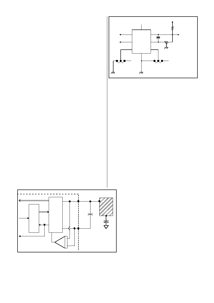
The QT switches and charge measurement hardware
functions are all internal to the QT114 (Figure 1-2). A 14-bit
single-slope switched capacitor ADC includes both the
required QT charge and transfer switches in a configuration
that provides direct ADC conversion. The burst length is
inversely proportional to the rate of charge buildup on Cs,
which in turn depends on the values of Cs, Cx, and Vcc. Vcc
is used as the charge reference voltage. Larger values of Cx
cause the charge transferred into Cs to accumulate more
rapidly. The trip points of the sensor can be changed by
altering Cs and Cx, the load capacitance. As a result, the
values of Cs, Cx, and Vcc should be fairly stable over the
expected operating temperature range.
Two fixed thresholds are used, one for low fluid level and the
other for high level; adjusting Cs and Cx to allow these to trip
at appropriate points is required by design, and if required
may be trimmed by an adjustment. Figure 1-1 shows the
optional potentiometer which can be used to fine-tune the
placement of these threshold points relative to the signal.
It is not necessary to use both detection threshold points; if
only single point sensing is desired, only the lower threshold
and OUT1 can be used, while ignoring OUT2.
Two option pins allow the selection of output polarity and the
insertion of a 'slosh filter' before the OUT pins, as shown in
Figure 1-1.
1.1 ELECTRODE DRIVE
The internal ADC treats Cs as a floating transfer capacitor;
as a direct result, the sense electrode can be connected to
either SNS1 or SNS2 with no performance difference. The
polarity of the charge buildup across Cs during a burst is the
same in either case. Cs must be of within a certain range for
proper operation.
It is possible to connect separate Cx and Cx' loads to SNS1
and SNS2 simultaneously, although the result is no different
than if the loads were connected together at SNS2 (or
SNS1). It is important to limit the amount of stray
capacitance on both terminals, especially if the load Cx is
already large, for example by minimizing trace lengths and
widths so as not to exceed the Cx load specification and to
allow for a larger sensing electrode size if so desired.
The PCB traces, wiring, and any components associated
with or in contact with SNS1 and SNS2 will become
proximity sensitive and should be treated with caution.
1.2 THRESHOLD POINTS
The QT114 employs twin threshold points set at both
250 (for T1) and 150 counts (for T2) of acquisition
signal. The signal travels in an inverse direction:
increasing amounts of Cx reduce the signal level; the
baseline ('dry') signal should lie at 300 counts or
more under most conditions. Calibration details are
discussed fully in Section 3.2.
2 ELECTRODE DESIGN
The QT114 is designed to operate with a 'plateau'
sensor, having a substantial surface area at each
desired trip point, to create a capacitive 'step'.
As Figure 2-1 shows, a vertical strip sensor on the
outside of a container (or a vertical, insulated rod in
the fluid) will generate a long sloping signal. The
desired trip point 'T' is subject to a great deal of
variation in location if the sensing signal drifts much,
- 2 -
Figure 1-1 Standard mode options
OUT 2
V
dd
V
dd
Cs
To 10x Scope Probe
To Electrode(s)
1M multi-turn
pot (optional)
2M (optional)
Gnd
OUT1
OUT2
FILT
Vcc
SNS2
SNS1
POL
POL: 1 = Active High
FILT: 1 = Slosh Filter
POLARITY
FILTER
1
2
3
4
5
6
7
8
OUT 1
Figure 1-2 Internal Switching & Timing
C
s
C
x
S NS 2
S NS 1
E LE C T RO DE
Si
n
g
l
e
-
S
l
o
p
e
1
4
-
b
it
S
w
i
t
c
hed
C
a
p
a
c
i
to
r
A
D
C
C ha rg e
A m p
B
u
rs
t
C
o
n
t
ro
l
l
e
r
Result
Done
Start

for example due to changes in Cs or Cx over the operating
temperature range.
Figure 2-2 shows the response from a horizontal strip of
the same surface area; the signal exhibits a very rapid rise
in signal between points l1 and l2. Variations in circuit
gain or signal drift have much less of an effect on the trip
point with this orientation.
In some cases (thin walled vessels for example) it may be
sufficient to have a small round or square electrode patch
on the exterior.
Figure 2-3 shows the response from a twin-level external
electrode set. The use of two horizontal electrode planes
or tiers creates well-defined trip points that can be used to
sense both 'low' and 'high' levels. A crossing of threshold
T1 will be reflected in the OUT1 signal, while T2 will be
reflected on OUT2.
2.1 EXTERNAL ELECTRODES
External electrodes should be electrically conductive;
metal foils and conductive carbon are both possible. Care
should be taken that other objects or people near the
vessel will not touch the electrode; in some cases
shielding around the electrode with grounded metal will be
required to prevent disturbances. If used, the shield
element should be spaced apart from the electrode by an
air gap or a low-density foam to reduce Cx loading.
The required surface area of the external electrode will
depend on the amount of signal needed to bracket the
detection threshold, which in turn will depend in part on Cs
and stray Cx. External electrodes sensing through thick
walls and/or sensing low permittivity fluids will require
larger surface areas than those sensing water through thin
plastic, for example. External electrodes are more likely to
require potentiometer trimming to achieve reliable
operation (Figure 1-1, also Section 3.2).
Note that external electrodes used with conductive
solutions (i.e. aqueous liquids) do not measure the
permittivity of the fluid: they actually measure the
permittivity of the vessel wall, between 2 plates: the
electrode (plate 1) and the fluid (plate 2, effectively a
variable-area ground plate): if the fluid were to be replaced
with mercury the signal would be unchanged. A 20%
thickness variation in the vessel wall will therefore
introduce about a 20% variation in the resulting
capacitance; if the vessel wall cannot be controlled
accurately enough in production, serious sensing errors may
occur.
When external electrodes are used to sense non-aqueous
substances (like oils or gasoline), the vessel wall dielectric
becomes a lessor contributor to the overall signal, which is
then heavily dominated by the permittivity of the fluid. The
lower the permittivity of the fluid the greater its dominance.
2.2 INTERNAL PROBES
When used with aqueous fluids or other electrically
conducting liquids, internal probes should be insulated with a
plastic layer. See also Section 2.1 for a discussion of
electrodes when used with conductive fluids. Aqueous
probes should be 100% insulated, even on the cut end of a
wire probe. The slightest pinhole of exposed metal anywhere
on an immersed part of the probe will immediately convert
the probe into a bare-metal probe (see Section 2.2.5).
Numerous types of internal point-level probes are possible.
2.2.1 D
ISC
P
ROBES
The simplest internal geometry is probably a disc probe
(Figure 2-4), having at least one planar surface ('tier')
parallel to the fluid surface. The sensing error can be
minimized by making the tier thin, so that the signal
transitions abruptly higher (see Figure 2-2) as the fluid
covers the tier.
A notable difficulty with disc probes is the task of insulating
them with a uniform, repeatable thickness of insulation.
2.2.2 S
PIRAL
W
IRE
P
ROBES
A spiral solid-wire probe is simple to construct (Figure 2-5),
and has the advantage of being pre-insulated in a wide
choice of plastics from inexpensive PVC to PTFE. These
probe types provide a large step-function of capacitance
localized at the desired trip point, and are easy to form.
Spiral wire probes are most effective in water-based fluids;
they are not as effective in oils and other nonconductive
substances.
- 3 -
Figure 2-1 Signal vs. Level for an External Vertical Strip
Figure 2-2 Signal vs. Level for an External Horizontal Strip
Figure 2-3 Signal vs. Level for Twin Horizontal Strips
Signal
Level
l
1
l
2
T
1
T
1
l
1
l
2
l
3
l
4
T
2
l
3
l
4
T
2
S ignal
Level
l
1
l
2
T
1
l
2
l
1
T
1
Signal
Level
l
1
l
2
T
1
l
1
l
2
T
1

Spiral wire probes have the disadvantage of not being as
rugged as a solid disc probe.
2.2.3 S
IDE
-E
NTRY
P
ROBES
Another type is a side-entry probe (Figure 2-8), which
requires an entry point into the vessel wall, but may have the
advantage of accessibility in certain cases. These can be
made of simple metal rod, insulated in almost any plastic if
required.
2.2.4 C
OAXIAL
P
ROBES
Another type of internal probe is the coaxial probe (Figure
2-10); these are most useful with oils or similar fluids having
a low dielectric constant; the inner rod is connected to the
signal connection, and together with the outer grounded
cylinder forms a capacitor whose dielectric is either air or oil.
Keeping the gap between rod and cylinder to a minimum
increases the 'gain' of the electrode.
Coaxial probes are more expensive to make, and can have
problems with vibration if they are not constructed robustly.
The outer cylinder should be perforated at key spots to allow
fluid to fill and drain the cavity without trapping air bubbles
inside. The outer cylinder can also be made of a wire mesh.
The outer cylinder does not have to be coated in plastic,
even when used with water-based fluids. When used with
oils, the inner rod does not require insulation either.
2.2.5 B
ARE
M
ETAL
P
ROBES
Bare metal internal probes can be used, for example with
nonconductive fluids like oils, without difficulty. This applies
to all probe types described above.
Bare probes can also be used with aqueous fluids, but in
these cases a 1,000pF (1nF) ceramic NPO capacitor should
be inserted between the probe and the QT114 to block DC
current flows.
A bare internal probe used with conductive fluids and an
in-line blocking capacitor will generate a huge, robust
capacitive response that will not readily permit the use of a
2-level probe due to signal saturation. Even the slightest
amount of bare metal exposed to the fluid will usually
generate an immediate, large response with aqueous fluids.
- 4 -
Figure 2-7 Twin-Level Internal Spiral Wire Probe
T
2
Figure 2-6 Twin-Level Internal Planar Probe
T
2
Figure 2-5 Single Level Internal Spiral Wire Probe
Figure 2-4 Single Level Internal Planar Probe

2.2.6 S
CALE
B
UILDUP
Scale buildup on internal probes, bare or insulated, is not
generally a problem since the sensor is still measuring
capacitance, not conductance, and a reduction in
conductivity around the probe will have minimal or no effect.
Probe designs should be tested for this to be certain in all
specific cases.
A legitimate concern with bare metal probes is the buildup of
scale or other deposits at the entry point of the probe into the
vessel. Such deposits may create a conductive surface path
(especially if the vessel is made of metal) that may lead to
false-positive trips. If the shank of the probe at the entry
point is insulated enough so that conductive bridging cannot
occur, this problem should be alleviated.
2.2.7 V
ISCOUS
, C
ONDUCTIVE
F
ILMS
Highly viscous fluids, or those having a high surface tension,
and having substantial conductivity can fool some electrode
designs into thinking that there is fluid present when there is
not. This is a particular problem with external electrodes,
where the residual films of certain types of fluids inside the
container, electrically coupled to the fluid mass below, will
create a substantial capacitive response. Internal probes are
much more resistant to this effect since the fluid surface is
guaranteed to become mechanically disconnected from the
probe when the level drops. Coating the inner vessel surface
with a smooth plastic of polyethylene or PTFE often has a
very beneficial effect on this phenomenon.
2.3 SINGLE LEVEL SENSING
When sensing for a single trip point, the single electrode can
be a simple horizontal strip on the outside of a nonmetallic
vessel (Figure 2-2), or an internal probe having a substantial
horizontal 'plateau' at the trip point (Figures 2-4, 2-5, 2-8,
2-10). When the strip or plateau is `covered' with fluid the IC
will detect on at least the OUT1 line; OUT2 can be ignored.
The trip point ideally occurs at the centerline of the internal
probe or external electrode; this can be trimmed with a
potentiometer if necessary (see Section 3.2). Making the
electrode narrow and long (horizontally) will help keep the
trip point localized within a narrow band.
- 5 -
Figure 2-11 Twin-Level Coaxial Probes For
Non-Aqueous Fluids
T
2
Figure 2-10 Coaxial Probe For Non-Aqueous Fluids
Figure 2-9 Twin-Level Internal Horizontal Probes
T
1
Figure 2-8 Single Internal Horizontal Probe