 | –≠–ª–µ–∫—Ç—Ä–æ–Ω–Ω—ã–π –∫–æ–º–ø–æ–Ω–µ–Ω—Ç: SY02-PLL | –°–∫–∞—á–∞—Ç—å:  PDF PDF  ZIP ZIP |
SYNCHRONOUS EQUIPMENT
CLOCK/SYNCHRONIZER - SY02-PLL
RALTRON ELECTRONICS CORP. 10651 N.W.19
th
St Florida 33172 U.S.A.
Tel: 305 593-6033 Fax: 305-594-3973 e-mail: sales@raltron.com Internet: http://www.raltron.com
SY02-PLL
Date: May 18, 2004
∑
INTRODUCTION
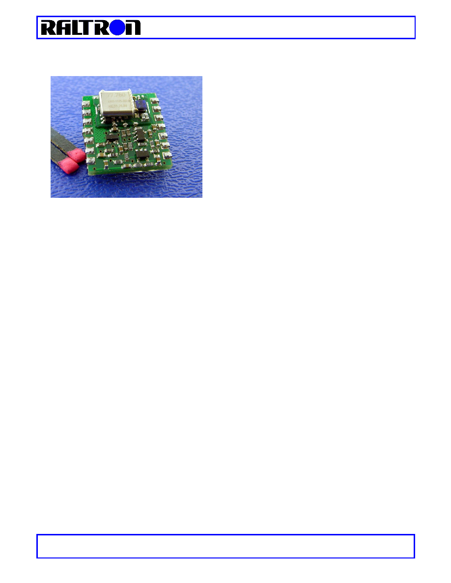
The SY02-PLL is a crystal-based PLL synchronizer designed
as a module level subsystem for easy incorporation into
telecommunication equipment.
∑
FEATURES
-
Low jitter output from intrinsically low jitter VCXO;
-
Four selectable references inputs: 8, 16, 32 and 64KHz;
-
Alarms and status;
-
Buffered reference output;
-
Tri-state (high impedance) reference and oscillators outputs;
-
Provides free running clock output;
-
The unit changes timing modes in response to external events;
-
J-TAG service port for re-programming and servicing;
∑
APPLICATIONS
-
ATM
-
SDH
-
PDH
-
SONET
-
other telecommunication equipment.

SYNCHRONOUS EQUIPMENT
CLOCK/SYNCHRONIZER - SY02-PLL
RALTRON ELECTRONICS CORP. 10651 N.W.19
th
St Florida 33172 U.S.A.
Tel: 305 593-6033 Fax: 305-594-3973 e-mail: sales@raltron.com Internet: http://www.raltron.com
∑
DESCRIPTION
The SY02-PLL is a Phase Lock Loop has been designed as a module level subsystem for easy incorporation into
telecommunication equipment. The module generates the output from a low jitter VCXO. The SY02-PLL can lock to
one of four reference frequencies from 8 to 64kHz that can be selected using to external select pins. The counters,
phase detector and other logic are implemented in programmable logic. The loop bandwidth is optimized according
to used VCXO and wanted output performance. The two output signals monitor the status of the phase loop LOL
(Loss of Lock) and LOR (Loss of Reference). The two control inputs provides module to go into free-run regardless
of the reference (FREE_RUN) and to the tri-state high impedance output (OUT EN). The SMD package dimensions
are 19.4 x 20.3 mm and power supply is 3.3V.
- INPUT REFERENCE SELECTION
IN-A IN-B REFERENCE
SELECTED
0
0
8KHz (default)
1 0
16KHz
0 1
32KHz
1 1
64KHz
- OUTPUT PROGRAMMING
EN OUT
FREE-RUN
OUTPUT
0
0
Locked to Reference
1 X
Hi-Z
Tri-State
0 1 Free-Run
- ALARM STATES
LOL LOR
ALARM
0
0
No alarm
1
0
Loss of Lock
0
1
Loss of Reference
MUX,
FPD,
Counters
&
Logic
LOOP
FILTER
VCXO
IN-A
IN-B
REF IN
LOR
REF OUT
J-TAG PORT
OUT
EN OUT
FREE-RUN
LOL

SYNCHRONOUS EQUIPMENT
CLOCK/SYNCHRONIZER - SY02-PLL
RALTRON ELECTRONICS CORP. 10651 N.W.19
th
St Florida 33172 U.S.A.
Tel: 305 593-6033 Fax: 305-594-3973 e-mail: sales@raltron.com Internet: http://www.raltron.com
∑
PIN DESCRIPTION
Pin #
Name
Description
1
REF OUT
Reference Output -> The buffered signal from REFERENCE IN pin.
2
TCK
J-TAG port for factory usage ≠ TCK
3
TMS
J-TAG port for factory usage ≠ TMS
4 GND
Ground
5
FREE-RUN
Free-Run -> Control input to force unit to run as free running oscillator
6
LOR
Loss of Reference -> Output signal shows presence of the reference
7
LOL
Loss of Lock -> Output signal shows status of the PLL
8
REF IN
Reference Input -> Reference input signal
9
OUT
Oscillator Output -> Output of the module
10
OUT EN
Output Enable -> Control input to enable/disable the module output
11
Vcc
Positive supply voltage
12
TDO
J-TAG port for factory usage ≠ TDO
13
IN-B
External Reference 1 Input -> Select input from reference 1
14
IN-A
External Reference 2 Input -> the input from reference 2
∑
ORDERING INFORMATION
o
Input/Output Frequencies available;
Frequency Suffix Frequency Suffix
8KHz F8
38.880MHz
O2
1.024MHz E0 44.4343MHz B1
1.544MHz T1 44.7360MHz T3
2.048MHz E1 51.8400MHz D1
4.096MHz E2 61.4400MHz U1
6.1760MHz T2 62.5000MHz G1
6.480MHz D1 65.5360MHz B2
8.192MHz E3 77.7600MHz O3
10.000MHz A1
12.800MHz S1
13.000MHz G1
15.000MHz A2
16.384MHz E4
19.440MHz O1
20.000MHz M1
20.1416MHz A3
20.4800MHz A4
22.2171MHz A5
26.0000MHz G2
27.0000MHz A6
29.4912MHz A7
32.768MHz E4
34.560MHz A8
37.0560MHz A9
SYNCHRONOUS EQUIPMENT
CLOCK/SYNCHRONIZER - SY02-PLL
RALTRON ELECTRONICS CORP. 10651 N.W.19
th
St Florida 33172 U.S.A.
Tel: 305 593-6033 Fax: 305-594-3973 e-mail: sales@raltron.com Internet: http://www.raltron.com
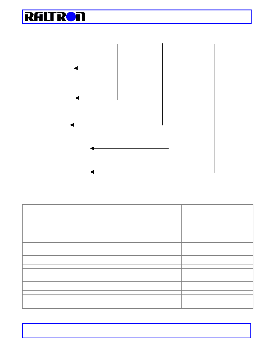
P/N System
SY02-PLL≠ IP < Input Frequency> - OU<Output Freq.>-S-T<Temp. Range>-P <Package Opt.>
See above Chart
If not listed Place
NL
and state
the Freq.)
See above Chart
(If Output Freq. Not applied place
NA
and state the Freq.)
Supply Voltage;
4
≠ 3.3V
Operating Temperature Range;
C
- 0∞C to 70∞C
I
-40∞C to +85∞C
Package Option;
J
≠ J Lead Package
S
- SMT Package
-
For other frequencies contact the factory!
-
When Input frequencies other than 8KHz are chosen IN-A and IN-B are disabled
∑
SPECIFICATION
General
Specifications
Mechanical 19.4 x 20.3 mm
SMT Module FR4 14pins dual-in-line
Power
3.3VDC,
<100mA
Regulated
Environment Operating Temperature
0∞C to 70∞C
(Extended Temp. available -40∞ to 85∞C)
Storage Temperature
-40∞ to 85∞C
Humidity
5% to 95% non-condensing
Internal Oscillators Voltage Controlled Crystal Oscillator
(VCXO)
Input Signals
Number of Reference Inputs 1
Input reference frequency 8, 16, 32 and 64kHz
Select by external pins
Signal Level HCMOS/TTL Compatible
Output Signals
Number of Outputs 2
Output 1 19.44, 38.88, 77.76MHz
User defined
Output 1 Signal Level HCMOS
Output 2 Buffered REF IN
Output 2 Signal Level HCMOS
Tracking/Capture
Range
±25ppm min
Signal Quality
Performance
Jitter generation <0.001UI
Jitter tolerance 2 µs, 10 Hz (0.05 UI @ 8KHz)
Frequency Output
Performance
Free run accuracy
±20ppm max. @ 25∞C
No reference signal
(***
±30ppm max. @ 25∞C at extended
operating temp. range***)
SYNCHRONOUS EQUIPMENT
CLOCK/SYNCHRONIZER - SY02-PLL
RALTRON ELECTRONICS CORP. 10651 N.W.19
th
St Florida 33172 U.S.A.
Tel: 305 593-6033 Fax: 305-594-3973 e-mail: sales@raltron.com Internet: http://www.raltron.com
∑
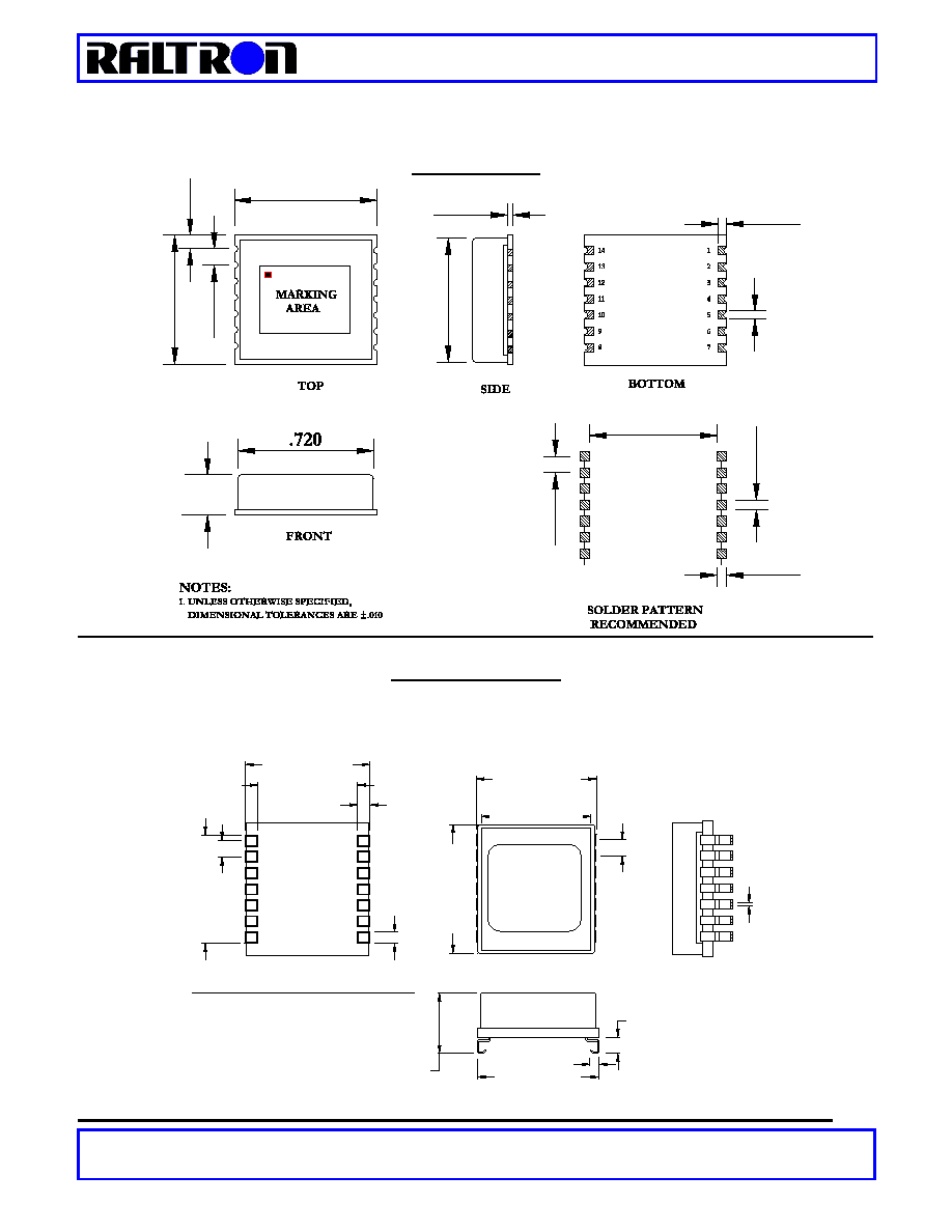
OUTLINE DRAWING
SMT VERSION
.100
.765
.037
.100
.605
.160±.005
.104
.760
.810
.078
.064
.098
.084
J-LEADS VERSION
.8
10 (2
0.57 mm)
1
.6
50 (1
6.51
mm)
.1
00 (2
.54mm)
.0
50 (1
.27 mm)
14
RECOMMENDED FOOTPRINT
.080 (2.03 mm)
.640 (16.26 m)
.800 (20.32 mm)
.780 (19.81 mm)
MARKING
LABEL
8
7
.1
00 (2
.54mm)
.0
180 (
.
46 mm)
.780 (19.81 mm)
.125 (3.17 mm)
.050 (1.28 mm)
Ty
p.
Ty
p.
Ty
p.
.720 (18.28 mm)
.285 (7.24 mm)