 | –≠–ª–µ–∫—Ç—Ä–æ–Ω–Ω—ã–π –∫–æ–º–ø–æ–Ω–µ–Ω—Ç: BA3836 | –°–∫–∞—á–∞—Ç—å:  PDF PDF  ZIP ZIP |
1
Multimedia ICs
Vocal fader IC
BA3836
Realizes karaoke functionality by enabling you to erase only the vocals from commercially available music software.
∑
Applications
Mini-components, radio cassette players, car stereos,
karaoke sets
∑
Features
1) Vocal fader functions (erase vocals from commer-
cially available music software) all on one chip.
2) Has internal secondary active LPF to enable a high-
degree of vocal cancellation (synchronous rejection
ratio) while retaining the same feeling.
3) Three control pins for switching between 4 modes:
through, vocal fader, sound multiplexing, and mute.
4) Key controller input and internal switches.
5) Internal microphone amplifier.
6) Low noise and low distortion.
7) Few external components.
∑
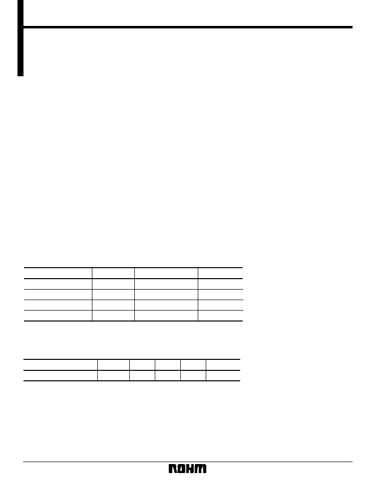
Absolute maximum ratings (Ta = 25∞C)
Parameter
Symbol
Limits
Unit
Power supply voltage
Power dissipation
Operating temperature
Storage temperature
V
CC
Max.
Pd
Topr
Tstg
18
1000
1
≠ 40 ~ + 85
≠ 55 ~ + 125
V
mW
∞
C
∞
C
1 Reduced by 10mW for each increase in Ta of 1
∞
C over 25
∞
C when mounted.
∑
Recommended operating conditions (Ta = 25∞C)
Parameter
Symbol
Unit
Max.
Typ.
Min.
Power supply voltage
V
CC
5.4
10
--
V
2
Multimedia ICs
BA3836
∑
Electrical characteristics (unless otherwise noted, Ta = 25∞C, V
CC
= 10V, f
IN
= 1kHz, V
IN
= 150mV, R
L
= 100k
)
Parameter
Symbol
Min.
Typ.
Max.
Unit
I
Q
1.6
2.6
3.3
mA
V
om
2.3
2.8
--
Vrms
G
VT
10
14
17
dB
G
VF
10
14
17
dB
G
VM
5
8
11
dB
CT
54
70
--
dB
MU
74
80
--
dB
SV
27
33
--
dB
THD
--
0.02
0.07
%
V
N
--
15
22
Vrms
R
IN
35
50
65
k
VthH
4.7
--
--
V
VthL
--
--
0.3
V
DCB
--
6
18
mV
DCC
--
6
18
mV
Quiescent current
Maximum output voltage
L / R gain
Low frequency gain
Microphone gain
Crosstalk
Mute attenuation
Vocal suppression rate
Total harmonic distortion
Noise level
Input impedance
Output switching
DC differential
Control pin threshold
(high)
Control pin threshold
(low)
Conditions
--
--
--
Through mode
THD = 1%, through mode
Through mode
f
IN
= 50Hz, vocal fader mode
f
IN
= 1kHz
f
IN
= 1kHz
Vocal fader mode
Through mode, BW: 400Hz to 30kHz
Rg = 0, DIN AUDIO
LIN, RIN, MICIN, FK
Pin 15 switching
Pin 16 switching
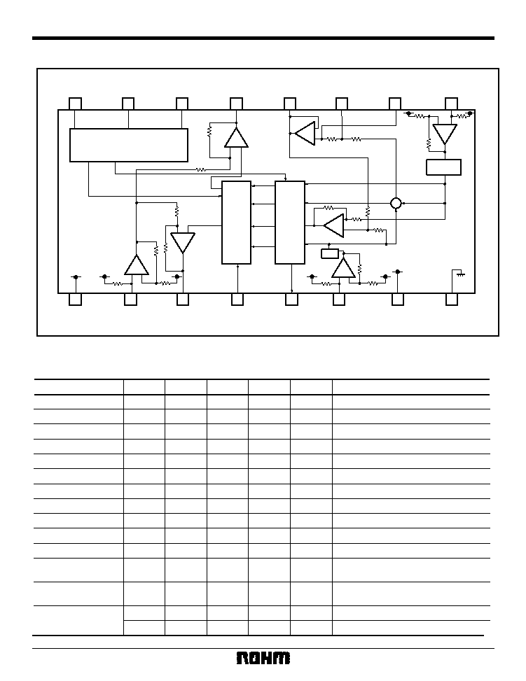
∑
Block diagram
SW2
LOGIC
SW1
+
≠
+
≠
SW3
R
L + R
L ≠ R
L
≠ +
≠
+
≠
+
≠ +
≠
+
SW4
1
2
3
4
5
6
7
+
8
16
15
14
13
12
11
10
9
C
B
A
R
OUT
LP
LP
LP
R
IN
V
CC
MIC
L
OUT
FK
TK
L
IN
BIAS
GND
3
Multimedia ICs
BA3836
∑
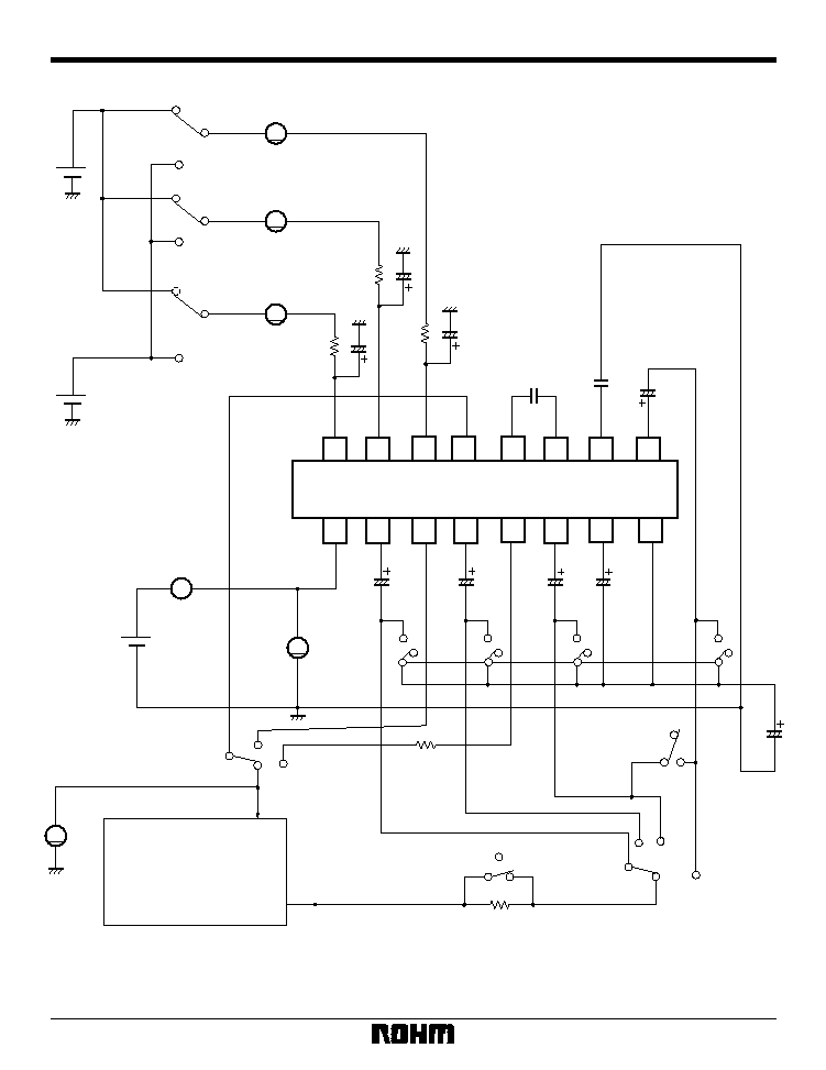
Measurement circuit
C
B
A
Rout
LP
LP
LP
R
IN
Vcc
MIC IN
L
OUT
FK
TK
L
IN
BIAS
GND
1
2
3
4
5
6
7
8
51k
51k
1
µ
51k
1
µ
0.22
µ
0.047
µ
10
µ
22
µ
10
µ
1
µ
4.7V
0.3V
C7
C5
C4
C3
C6
10
µ
C2
1
µ
C1
R
L
FK
MIC
10
µ
51k
600
OSC
100k
MEASUREMENT
AUDIO
ANALYZER
V
1k
A
A
A
A
V
V
13
12
14
11
10
9
15
16
Fig.1
4
Multimedia ICs
BA3836
∑
Circuit operation
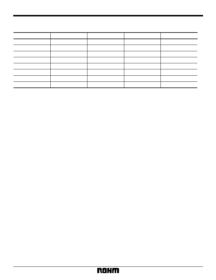
Mode table (A: pin 14, B: pin 15, C: pin 16)
Mute
Vocal fader
Sound multiplexing
Through
Sound multiplexing
Vocal fader
Sound multiplexing
L + R
A B C
0 0 0
0 0 1
0 1 0
0 1 1
1 0 0
1 0 1
1 1 0
1 1 1
LOUT
ROUT
TK
MUTE
VF
L
L
KC
KC
KC
KC
MUTE
VF
L
R
KC
KC
KC
KC
MUTE
VF
L
L
R
VF
L
L + R
MODE
0: 0V
1: 5V
VF: Vocal fader output
KC: Signal passed through key controller
(1) Microphone output is not muted during muting (ABC = 000 or 100).
(2) For the gain and relative phase, see block diagram.
1) L / R input and output in the through mode are synchronous with a gain of 14dB.
2) L / R input and TK output in the key controller mode are synchronous with a gain of 8dB.
3) L / R output and FK input in the key controller mode are synchronous with a gain of 6dB.
4) MIC input and L / R output are negative phase with a gain of 8dB.
5
Multimedia ICs
BA3836
1
µ
10
µ
10
µ
0.047
µ
0.22
µ
1k
1
µ
µ
- COM
51k
1
µ
51k
1
µ
51k
POWER
AMP
MICROPHONE
MICROPHONE
Key-con
TAPE,CD
LD,etc.
1
2
3
4
5
6
7
8
+
13
12
14
11
10
9
15
16
Fig.2
∑
Operation notes
(1) We guarantee the application circuit design, but rec-
ommend that you thoroughly check its characteristics in
actual use. If you change any of the external compo-
nent values, check both the static and transient charac-
teristics of the circuit, and allow sufficient margin in your
selections to take into account variations in the compo-
nents and ICs.
(2) The vocal fader works by canceling out the synchro-
nous component of the signal, leaving the low compo-
nents in place. Consequently, the vocal fader may not
be very effective with certain recordings.
(3) In cases where output DC differential can cause
noise when switching between modes, use a time con-
stant for the timing of control pin switching, or take
some other measure.
(4) Operating supply voltage may vary according to
ambient temperature. Using this IC outside the recom-
mended supply voltage range may result in increased
crosstalk or mute attenuation.
∑
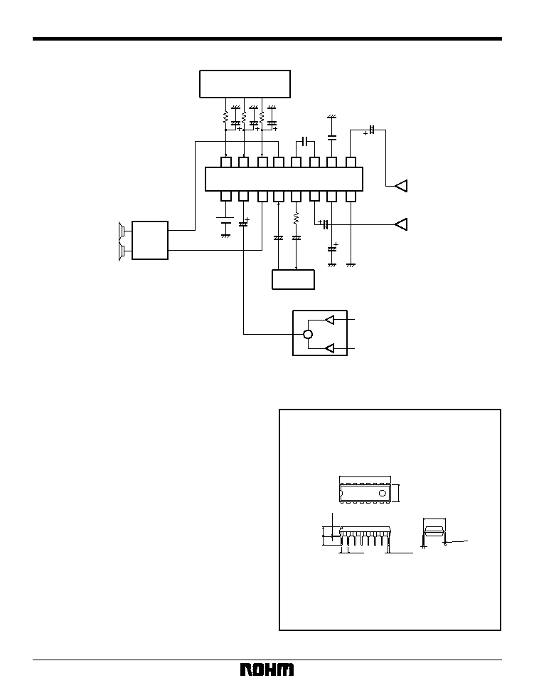
Application example
DIP16
0.51Min.
0.3
±
0.1
9
16
8
1
6.5
±
0.3
3.2
±
0.2
4.25
±
0.3
0.5
±
0.1
19.4
±
0.3
2.54
0
∞
~ 15
∞
7.62
∑
External dimensions (Units: mm)