505
Motor driver ICs
BA6259N
F
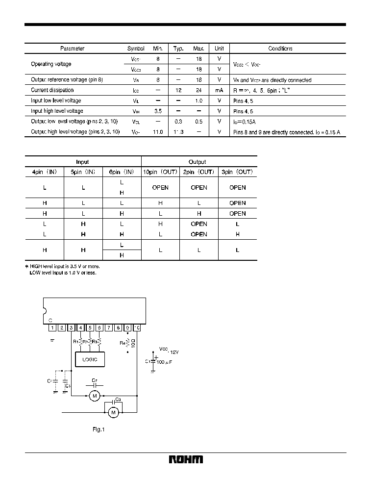
Electrical characteristics (unless otherwise noted, Ta = 25
_
C and V
CC
= 12V)
F
Input / output truth table
F
Application example
C
2
, C
3
: Capacitors for preventing parasitic oscillation.
Though the optimum capacitance depends on such PCB
arrangement factors as the power supply circuit, motor
characteristics, and conductor foil patterns, a range of
0.01
X
1
�
F is recommended.
C
4
, C
5
: Capacitors for preventing parasitic oscillation.
They may or may not be required, depending on the PCB
arrangement. A capacitance range of 0.01
X
10
�
F is rec-
ommended.

506
Motor driver ICs
BA6259N
F
Control pin equivalent circuit
F
Oparation notes
(1)
Use the BA6259N with V
R
(pin 8) short-circuited to
V
CC2
(pin 9). The V
CC2
potential should be lower than the
V
CC1
potential. Under these conditions, the IC provides a
HIGH level output voltage of 11.3V (typical, V
CC2
=12V).
Because a single transistor is used for the low-side out-
put stage, the LOW level output voltage is further low-
ered. This results in a wide range of motor drive voltage.
(2)
Though the IC input pins can be directly connected
with MOS output pins, it is recommendable to connect re-
sistors of a few kiloohms to do3en of kiloohms between
the pins for the sake of pin protection.
(3)
Due to the effects of capacitors C
2
X
C
5
, the motor
that is not being driven could be momentarily driven dur-
ing mode switching. Check for this problem when design-
ing your application.
(4)
It is recommendable to arrange your design so that
voltage rises at V
CC1
prior to V
CC2
when turning on the
power, and voltage falls at V
CC1
after V
CC2
when turning
off the power.
(5)
Thermal shutdown circuit
When the thermal shutdown circuit is activated, the out-
put is left OPEN. The circuit is activated when the IC junc-
tion temperature rises above 170
_
C. The temperature
difference between the activation and deactivation set-
tings is about 30
_
C.
(6)
The quality of these products have been carefully
checked; however, use of the products with applied volt-
ages, operating temperatures, or other parameters that
exceed the absolute maximum rating given may result in
the damage of the IC and the product it is used in. If the
IC is damaged, the short mode and open modes cannot
be specified, so if the IC is to be used in applications
where parameters may exceed the absolute maximum
ratings, then be sure to incorporate fuses, or other physi-
cal safety measures.
(7)
Input pins
Voltage should never be applied to the input pins when
the V
CC
voltage is not applied to the IC. Similarly, when
V
CC
is applied, the voltage on each input pin should be
less than V
CC
and within the guaranteed range for the
electrical characteristics.
(8)
Back-rush voltage
Depending on the ambient conditions, environment, or
motor characteristics, the back-rush voltage may fluctu-
ate. Be sure to confirm that the back-rush voltage will not
adversely affect the operation of the IC.

507
Motor driver ICs
BA6259N
(9)
Large current line
Large currents are carried by the motor power supply and
motor ground for these ICs.
Therefore, the layout of the pattern of the PC board and
the constants of certain parameters for external compo-
nents, such as the capacitor between the power supply
and ground, may cause this large output current to flow
back to the input pins, resulting in output oscillation or
other malfunctions. To prevent this, make sure that the
PC board layout and external circuit constants cause no
problems with the characteristics of these ICs.
(10) Power dissipation
The power dissipation will fluctuate depending on the
mounting conditions of the IC and the ambient environ-
ment. Make sure to carefully check the thermal design of
the application where these ICs will be used.
(11) Power consumption
The power consumption by the IC varies widely with the
power supply voltage and the output current. Give full
consideration to the power dissipation rating and the
thermal resistance data and transient thermal resistance
data, to provide a thermal design so that none of the rat-
ings for the IC are exceeded.
(12) ASO
Make sure that the output current and supply voltage do
not exceed the ASO values.
(13) Precautions for input mode switching
To ensure reliability, it is recommended that the mode
switching for the motor pass once through the open
mode.
(14) In-rush current
There are no circuits built into these ICs that prevent in-
rush currents. Therefore, it is recommended to place a
current limiting resistor or other physical countermea-
sure.
(15) Factors regarding the thermal, power supply, and
motor conditions
If the potential of the output pin sways greatly and goes
below the potential of ground, the operation of the IC may
malfunction or be adversely affected. In such a case,
place a diode between the output and ground, or other
measure, to prevent this.

