445
Motor driver ICs
Reversible motor driver
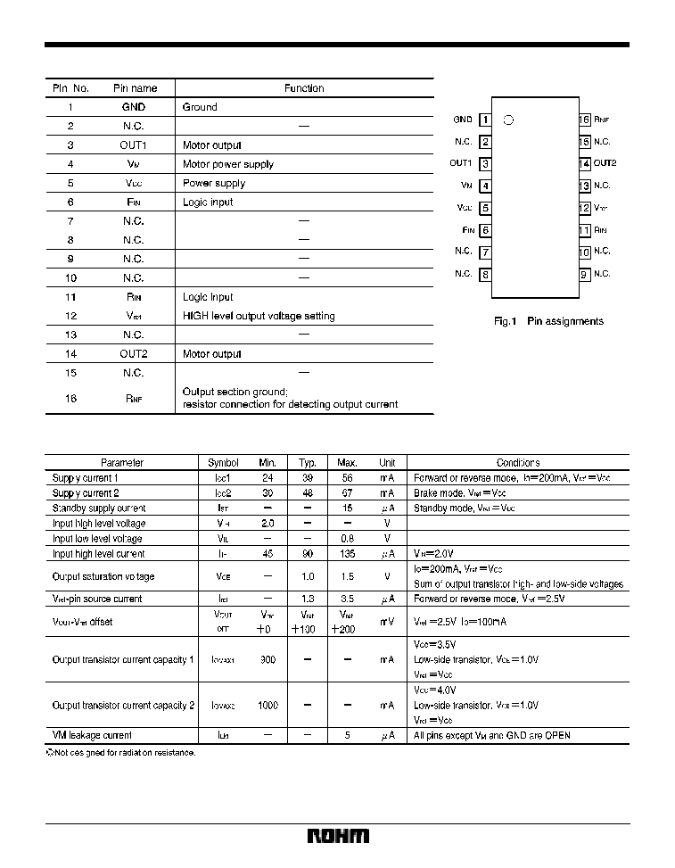
BA6288FS
The BA6288FS is a reversible-motor driver with a maximum output current of 1.0A. Two logic inputs allow four output
modes: forward, reverse, stop (idling), and brake. A built-in power saving circuit suppresses current consumption when
the motor is in stop mode.
F
Applications
Compact, low-current DC motors and portable equipment such as camcorders
F
Features
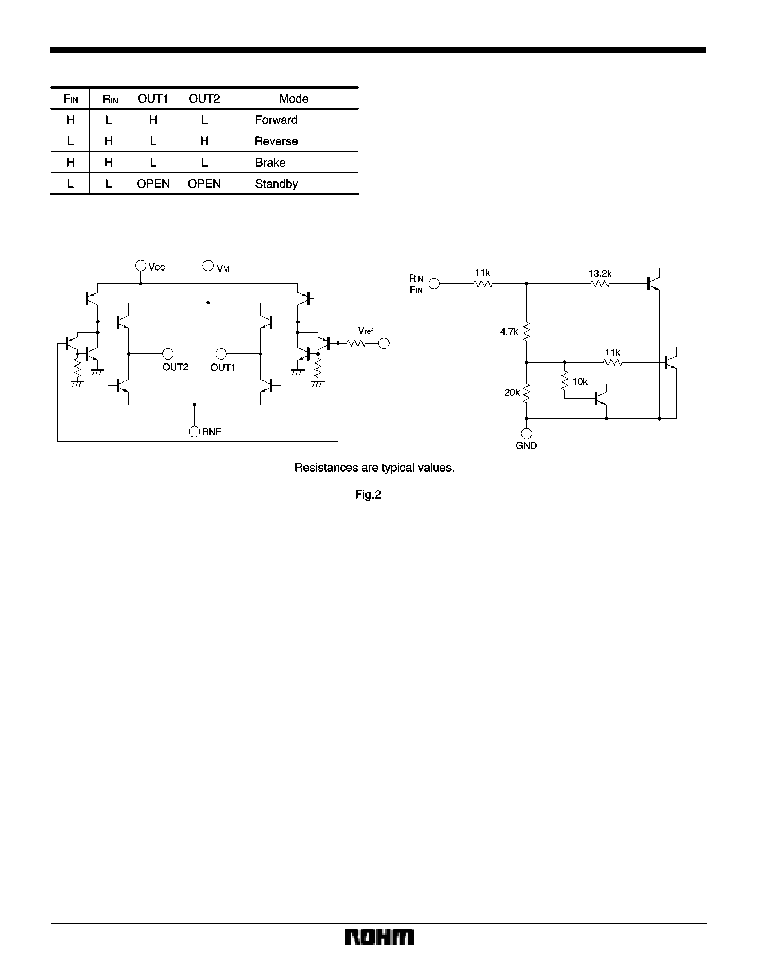
1) Two logic inputs allow four output modes: forward, re-
verse, stop (idling), and brake.
2) Built-in power saving circuit suppresses the stop
mode current dissipation.
3) Output voltage can be set arbitrarily with the V
REF
pin.
4) Interfaces with TTL devices.
5) Built-in thermal shutdown circuit turns off all circuits
when high IC junction temperature is detected.
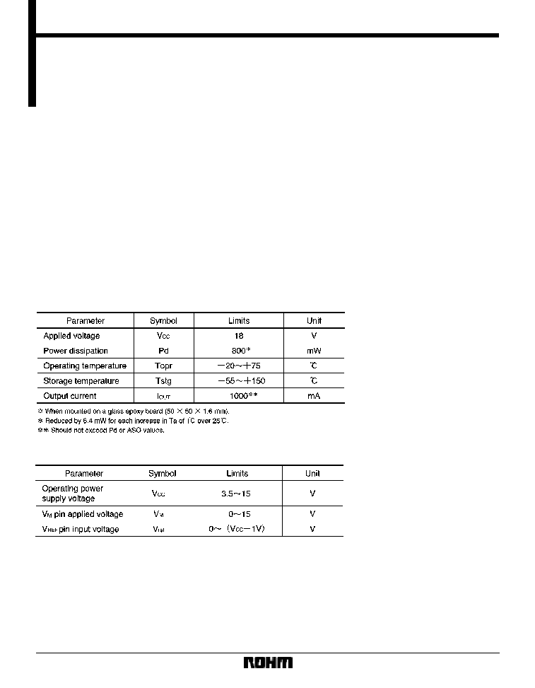
F
Absolute maximum ratings (Ta = 25
_
C)
F
Recommended operating conditions

449
Motor driver ICs
BA6288FS
F
Operation notes
(1)
The quality of these products have been carefully
checked; however, use of the products with applied volt-
ages, operating temperatures, or other parameters that
exceed the absolute maximum rating given may result in
the damage of the IC and the product it is used in. If the
IC is damaged, the short mode and open modes cannot
be specified, so if the IC is to be used in applications
where parameters may exceed the absolute maximum
ratings, then be sure to incorporate fuses, or other physi-
cal safety measures.
(2)
GND potential
The potential for pin 1 must be kept lower than the poten-
sials ofthe other pins regardless of the circumstances.
(3)
Input pins
Voltage should never be applied to the input pins when
the V
CC
voltage is not applied to the IC. Similarly, when
V
CC
is applied, the voltage on each input pin should be
less than V
CC
and within the guaranteed range for the
electrical characteristics.
(4)
Back-rush voltage
Depending on the ambient conditions, environment, or
motor characteristics, the back-rush voltage may fluctu-
ate. Be sure to confirm that the back-rush voltage will not
adversely affect the operation of the IC.
(5)
Large current line
Large currents are carried by the motor power supply and
motor ground for these ICs.
Therefore, the layout of the pattern of the PC board and
the constants of certain parameters for external compo-
nents, such as the capacitor between the power supply
and ground, may cause this large output current to flow
back to the input pins, resulting in output oscillation or
other malfunctions. To prevent this, make sure that the
PC board layout and external circuit constants cause no
problems with the characteristics of these ICs.
(6)
Power dissipation
The power dissipation will fluctuate depending on the
mounting conditions of the IC and the ambient environ-
ment. Make sure to carefully check the thermal design of
the application where these ICs will be used.
(7)
Power consumption
The power consumption by the IC varies widely with the
power supply voltage and the output current. Give full
consideration to the power dissipation rating and the
thermal resistance data and transient thermal resistance
data, to provide a thermal design so that none of the rat-
ings for the IC are exceeded.
(8)
ASO
Make sure that the output current and supply voltage do
not exceed the ASO values.
(9)
Precautions for input mode switching
To ensure reliability, it is recommended that the mode
switching for the motor pass once through the open
mode.
(10) In-rush current
There are no circuits built into these ICs that prevent in-
rush currents. Therefore, it is recommended to place a
current limiting resistor or other physical countermea-
sure.
(11) Factors regarding the thermal, power supply, and
motor conditions
If the potential of the output pin sways greatly and goes
below the potential of ground, the operation of the IC may
malfunction or be adversely affected. In such a case,
place a diode between the output and ground, or other
measure, to prevent this.