324
Optical disc ICs
4-channel BTL driver for CD players
BA6392FP
The BA6392FP is a 4-channel BTL driver for CD player motors and actuators. It has an internal primary filter, and can
be directly connected (without attached components) to the servo PWM output of all drivers other than the spindle driver.
The BA6392FP is pin compatible with the BA6297AFP.
F
Applications
CD players, CD-ROM drives
F
Features
1) HSOP 28-pin package allows for miniaturization of
applications.
2) PWM input is filtered by the internal primary filter,
eliminating the need for attached resistors and ca-
pacitors, thereby helping reduce the number of com-
ponents. Resistor and capacitor time constants can
also be changed with attached components.
3) Internal thermal shutdown circuit.
4) Internal mute circuit.
F
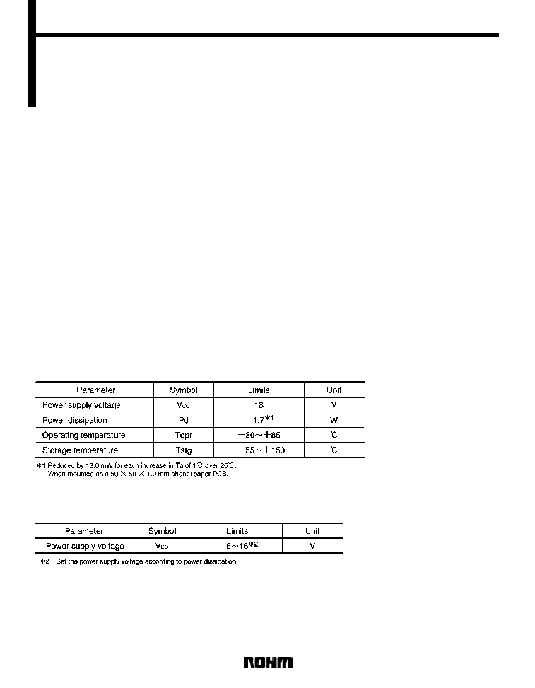
Absolute maximum ratings (Ta = 25
_
C)
F
Recommended operating conditions (Ta = 25
_
C)

325
Optical disc ICs
BA6392FP
F
Block diagram

326
Optical disc ICs
BA6392FP
F
Pin descriptions
327
Optical disc ICs
BA6392FP
F
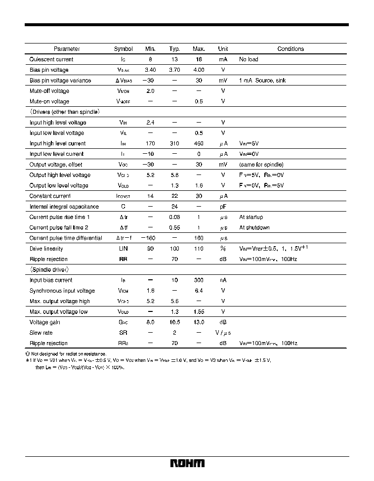
Electrical characteristics (unless otherwise noted, Ta = 25
_
C, V
CC
= 8V, f = 1kHz, R
L
= 8
)

328
Optical disc ICs
BA6392FP
F
Input / output circuits
F
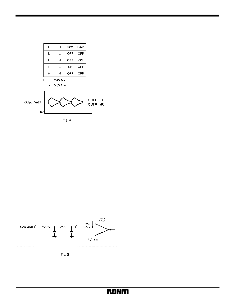
Circuit operation
(1)
Fig. 3 shows the inputs from the digital servo IC for
CH1-CH3 drivers (all drivers except the spindle).
SW1 is on when the forward input signal (HIGH level,
over 2.4V) is present. SW2 is on when the reverse input
signal is present (Fig. 2)
The constant current (I
1
) at this time enters the RC and
generates an integral waveform based on the duty of the
input waveform. The BTL is output from BUF1 and BUF2
(Fig. 4).
To maintain the HIGH level with forward (or reverse) in-
put, the DC voltage generated at point A is :
I
1
R 2.5V (reverse :
*
2.5V)
This is the voltage generated relative V
REF
. The setting is
such that a voltage differential of 5V is generated be-
tween output pins. The time constant is :
R
C = 2.4
�
sec
329
Optical disc ICs
BA6392FP
This can be increased by inserting a capacitor between
point A (pins 3, 11 and 18) and V
REF
. The constant current
(Iconst) given in the electrical characteristics refers to I
1
and I
2
in Fig. 2.
(2)
CH4 driver (spindle driver)
Pins 23 and 25 are shorted inside the IC. Bias amplitudes
are the primary type of inputs assumed. The level shift
circuit converts the pre-stage amplifier output (centered
on the bias level and impressed on pins 23 and 25) to
positive and negative amplitudes centered on V
REF
. The
level shift circuit's output is BTL-output from the buffer
amplifier.
Because of the high input impedance, the IC is designed
to accommodate a filter comprising attached resistors
and capacitors.
F
Operation notes
(1)
The BA6392FP has an internal thermal shutdown
circuit. Output current is muted when the chip tempera-
ture exceeds 180
_
C (typically).
(2)
The output current can also be muted by lowering
the mute pin (pin 15) voltage below 0.5V.
(3)
All four driver output channels are muted during
thermal shutdown, muting and a drop in bias pin voltage.
No other components are muted.
(Example) For secondary filters
330
Optical disc ICs
BA6392FP
F
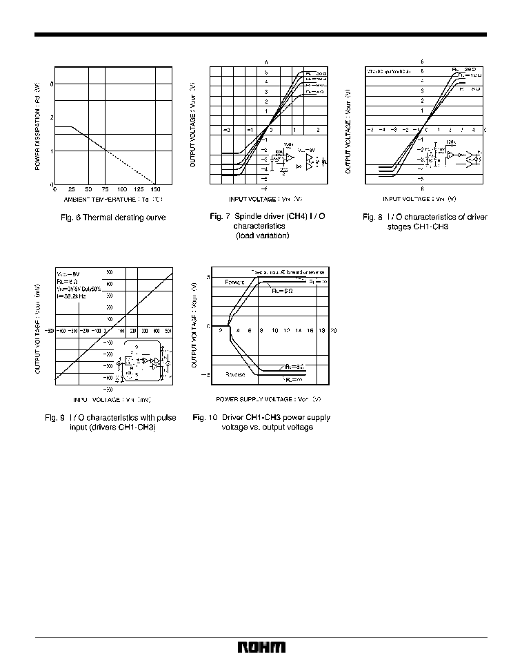
Electrical characteristics curves

F
External dimensions (Units: mm)
331
Optical disc ICs
BA6392FP