
695
Motor driver ICs
2-phase half-wave motor predriver
BA6406F
The BA6406F is a 2-phase, half-wave motor predriver suited for fan motors.
F
Features
1) Lock detection and rotational speed sensing mecha-
nisms are built in.
2) Compact 8-pin SOP package reduces the number of
external components required.
3) Automatic restart when the motor lock is undone.
4) Hall inputs have a hysteresis.
F
Absolute maximum ratings
F
Operating power supply voltage (Ta = 25
_
C)
696
Motor driver ICs
BA6406F
F
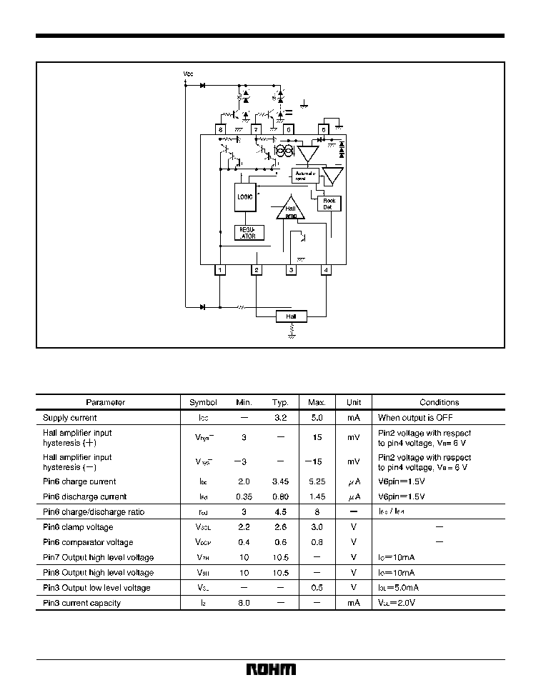
Block diagram and application example
F
Electrical characteristics (unless otherwise noted, Ta = 25
_
C and V
CC
= 12V)

697
Motor driver ICs
BA6406F
F
Lock detection
The automatic restart circuit detects a motor lock condi-
tion and automatically turns off the output current. When
the lock condition is cleared, the IC automatically restarts
and allow the motor to run.
In the BA6406F, automatic restart is performed in the fol-
lowing manner. A motor lock condition is detected when
the Hall signal stops switching. The output is ON when
pin 6 is being charged, and OFF when pin 6 is being dis-
charged. Pin 3 is ON during normal operation, and OFF
when the motor is locked. Pin 3 is an open collector out-
put.
Output ON time (t
ON
) and OFF time (t
OFF
) determined by
the pin6 capacitor
where
C is the capacitance of the pin-6 external capacitor
V
6CL
is the pin6 clamp voltage
V
6CP
is the pin6 comparator voltage
I
6C
is the pin6 charge current
I
6d
is the pin6 discharge current
I
6C
t
ON
=
C
S
(V
6CL
*
V
6CP
)
(sec)
I
6d
t
OFF
=
C
S
(V
6CL
*
V
6CP
)
(sec)
698
Motor driver ICs
BA6406F
F
Operation notes
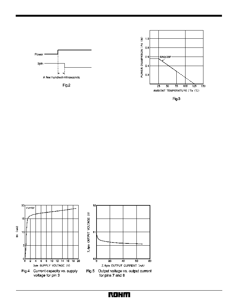
(1)
The lock detection output pin (pin 3) may maintain
HIGH level for a few hundred milliseconds when the pow-
er is turned on.
(2)
Allowable power dissipation
The allowable power dissipation is plotted against ambi-
ent temperature in Fig. 3.
(3)
Power dissipation
Power consumed in the I
C
can be calculated from the fol-
lowing equation:
P
C
= P
C1
+P
C2
+P
C3
(
1) P
C1
is power consumed by the circuit current.
P
C1
= V
CC
I
CC
(
2) P
C2
is the output current consumption.
P
C2
= (V
CC
*
V
OH
)
I
O
V
OH
is the HIGH level voltage of pins 7 and 8. Power dis-
sipation can be reduced by raising the hfe-rank of the ex-
ternal output transistor and thereby reducing the I
O
value.
(
3) P
C3
is power consumed by pin 3.
P
C3
= V
3L
I
3
where V
3L
is the pin-3 LOW level voltage and I
3
is the
pin-3 current. Make sure that your application does not
exceed the allowable power dissipation of the IC.
F
Electrical characteristic curves

699
Motor driver ICs
BA6406F
F
External dimensions (Units: mm)