611
Motor driver ICs
3-phase motor driver
BA6463FP-Y
The BA6463FP-Y is a motor driver developed for cylinders, which a constant power supply of 5V, and the start and stop
pins which opens output are incorporated.
F
Applications
VCR cylinder motors
F
Features
1) 3-phase, full-wave, pseudo-linear drive system.
2) Internal constant voltage power supply. (5V)
3) Internal thermal shutdown circuit.
F
Block diagram
612
Motor driver ICs
BA6463FP-Y
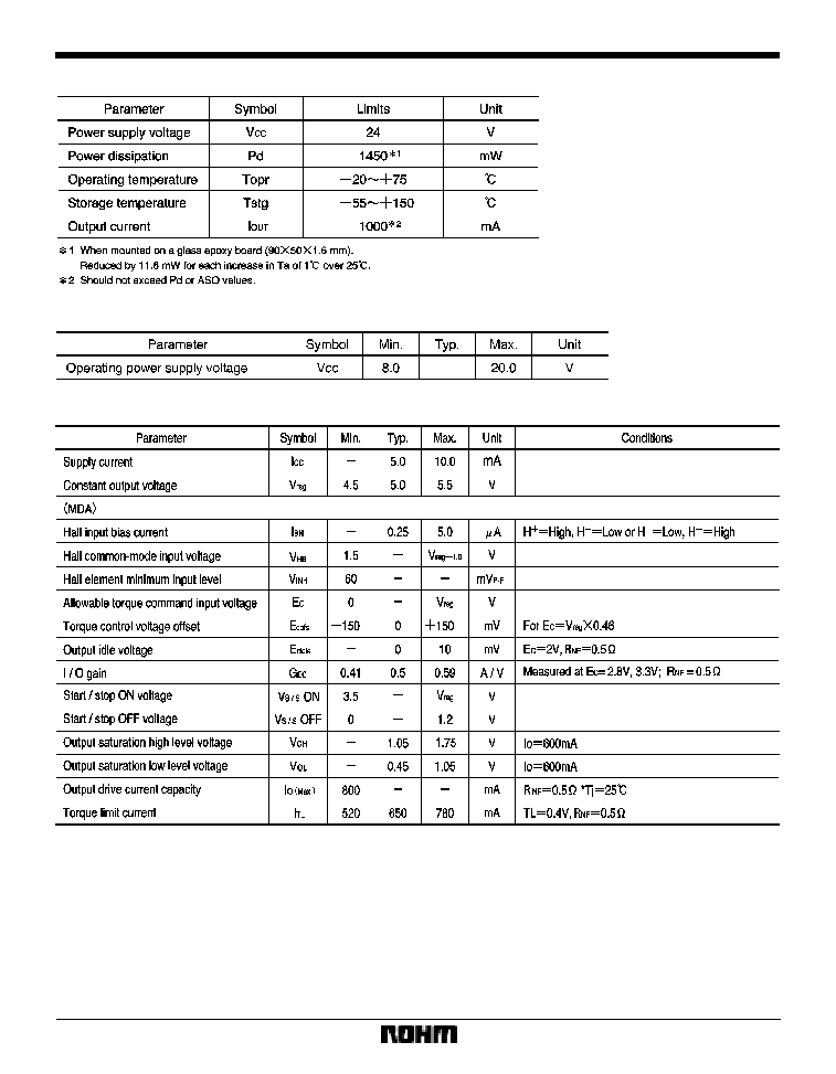
F
Absolute maximum ratings (Ta = 25
_
C)
F
Recommended operating conditions (Ta = 25
_
C)
F
Electrical characteristics (unless otherwise noted, Ta = 25
_
C, V
CC
= 12V)

615
Motor driver ICs
BA6463FP-Y
F
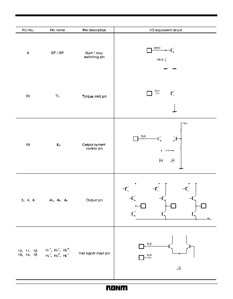
Circuit operation
(1)
Hall I / O
The 3-phase Hall signal is amplified in the hall amplifiers
and sent to the matrix circuit, where the signal is further
amplified and combined. After the signal is converted to
a current in the amplitude control circuit, the current is
supplied to the output driver, which then provides a motor
drive current. The phases of the Hall input signal, output
voltage, and output current are shown in Fig. 1.
(2)
Torque control pin (EC pin)
The output current can be controlled by adjusting the
voltage applied to the torque control pin.
(3)
Start / stop pin
The motor is in the run mode when the pin input voltage
is 3.5V or more and in the standby mode (all output tran-
sistors are off) when the voltage is 1.2V or less.
(4)
Power ground pin (R
NF
pin)
The R
NF
pin is the output stage ground pin. Connect a re-
sistor (0.5
recommended) between this pin and the
ground to monitor the output current.
(5)
Phase compensation pin (C
NF
pin)
Connect a capacitor between this pin and V
CC
if the out-
put tends to oscillate.
F
Application example