1
Video ICs
VIF / SIF signal processor
BA7357S
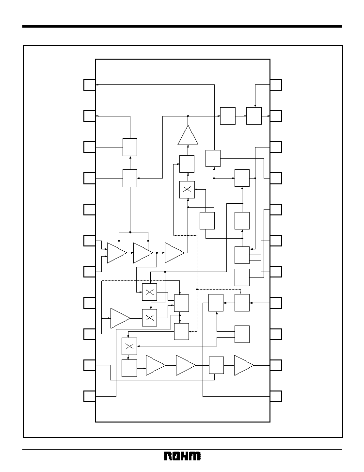
The BA7357S is a multi-format (M, B / G, D / K, and I) VIF / SIF signal processor for television and VCR applications.
It features a built-in sound-trap and band-pass filters, and employs a pulse-count audio detector that does not require
adjustment. This IC reduces external component requirements, and allows space savings.
∑
Applications
TVs and VCRs
∑
Features
1) Separate-carrier PLL with full synchronous detec-
tion. Excellent DG / DP, CS beat (920kHz) and
cross color. In addition, by pulling down the SIF
input (pin 9) it can be used as an intercarrier.
2) The IF AGC time constant is dual-layered to allow
faster speeds.
3) The variable-gain amplifier has excellent linearity to
ensure low distortion, and AGC variance and tem-
perature drift have been minimized.
4) Significant improvement in image quality through
use of a filter that reduces CS beat.
5) Built-in SOUND filter (4.5MHz SOUND Trap and
4.5MHz SOUND BPF).
The MODE switch can be used to switch the
SOUND filter frequency band to match the transmis-
sion format (M: 4.5, B / G: 5.5, I: 6.0, D / K:
6.5MHz).
6) The audio detector uses a pulse-counter detector
that does not require adjustment, eliminating the
need for a detector coil. Broad S-curve for multiplex
broadcast compatibility.
7) Use of pulse-counter detection and the built-in
SOUND filter means fewer pins, external compo-
nents and adjustment locations are required. The IC
is available in a 22-pin SDIP package and will
enable cost and space savings.
∑
Absolute maximum ratings (Ta = 25∞C)
∑
Recommended operating conditions (Ta = 25∞C)
Parameter
Symbol
Limits
Unit
V
CCMax.
V
Pd
Max.
10.5
1
1250
2
mW
Topr
≠ 15 ~ + 70
∞
C
Tstg
≠ 40 ~ + 150
∞
C
V
P2Max.
10.5
V
Applied voltage
Power dissipation
Operating temperature
Storage temperature
Pin 2 applied voltage
1 24
resistor connected between V
CC
and V
reg
.
2 Reduced by 10mW for each increase in Ta 1
∞
C over 25
∞
C.
Parameter
Symbol
Limits
Unit
8.8 ~ 9.2
1
V
11.7 ~ 12.3
2
V
8.5 ~ 9.5
1
V
CC9V
V
CC12V
V
CC
V
Power supply voltage (9V)
Power supply voltage (12V)
Guaranteed operating power
supply voltage
1 24
resistor connected between V
CC
and V
reg.
2 56
resistor connected between V
CC
and V
reg.

4
Video ICs
BA7357S
∑
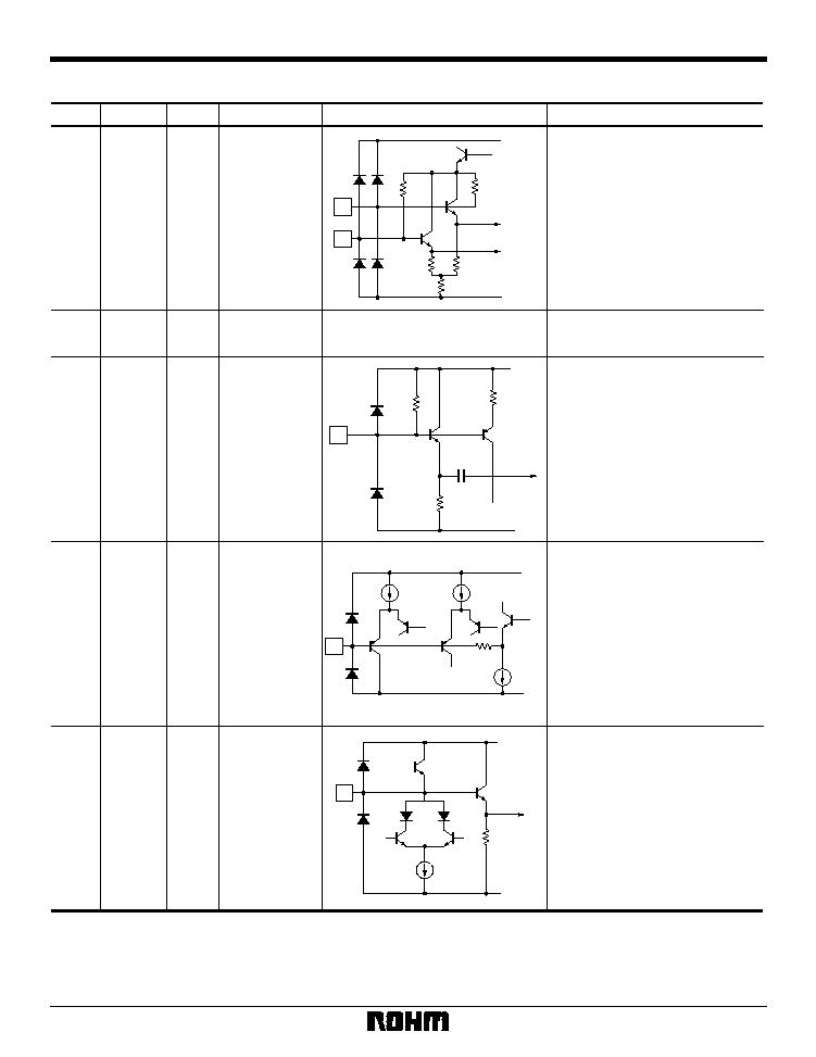
Equivalent circuits
V
CC
and V
CC
2 in the equivalent circuit diagrams are connected to the Vreg terminal (pin 18).
AFT output.
Vreg / GND push-pull output.
RFAGC output.
Open-collector output. Gain can be
set using an external resistor
(minimum value of the maximum sink
current of pin 2 is 0.7mA) . Keep the
pin 2 voltage at 10.5V or less.
RFAGC delay point adjustment.
Connect to GND via a variable
resistor (approx. 100k
).
For filter time constant for VIFAGC.
2.7V
(when 100k
resistor
connected)
1
AFTOUT
OUT
--
OUT
--
--
--
5.0V
--
--
0V
2
RFAGC
3
AGCADJ
4
AGCFLT
5
GND1
Pin name
Pin No.
IN / OUT Standard voltage
Function
Equivalent circuit
GND terminal for VIF, AGC and AFT.
V
CC
GND
500
1k
1
500
2
V
CC
GND
4k
3
V
CC
GND
4.5k
4k
25.2k
1k
4
400
V
CC
GND
5
Video ICs
BA7357S
7
VIFA
6
VIFB
IN
4.2V
8
GND2
--
--
0V
IN
6.6V
--
2.7V
--
5.2V
9
SIF
10
AFC
11
VO4.5M
Standard voltage
IN / OUT
Video IF input.
Use with balanced input.
SIF and PLL GND.
Audio IF input.
Can set to intercarrier mode by
pulling down via a 2k
resistor.
Terminal for holding the audio
output DC level fixed.
Connect to GND via a 4.7
µ
F
capacitor and to Vreg via a 10
µ
F
capacitor to reduce BUZZ.
Set this pin to 0.3V or lower to
apply Audio / Video Mute.
2nd SIF output.
Connect a Trap to this pin to vary
the Sound Filter characteristics.
The internal impedance is a high
(Approximately) 1k
, so connect a
Buffer to output.
Pin name
Pin No.
Function
Equivalent circuit
5
7
V
CC
GND
1k
1k
1k
5.3k
5.3k
9
20k
15k
15k
17pF
V
CC
GND
10
3.5V
40k
V
CC
GND
11
V
CC
GND
Sound
Filter
8k