 | –≠–ª–µ–∫—Ç—Ä–æ–Ω–Ω—ã–π –∫–æ–º–ø–æ–Ω–µ–Ω—Ç: BA7725 | –°–∫–∞—á–∞—Ç—å:  PDF PDF  ZIP ZIP |
1
Multimedia ICs
Analog compander for KARAOKE
echo systems
BA7725S / BA7725FS
The BA7725S and BA7725FS are analog companders designed for KARAOKE echo systems, and logarithmically
compress the signal level by 1 / 2 and then logarithmically expand it by a factor of 2. These ICs can be used in com-
bination with the BU9252S or BU9252F to create a digital echo system. These ICs have an internal line mixer ampli-
fier for mixing line input and echo signals. The internal electronic volume control makes it possible to adjust the mixer
level and loop level mixer with an external DC voltage.
∑
Applications
Circuits that require analog signal compression and expansion
∑
Features
1) Internal logarithmic 1 / 2 compression circuit and 2
◊
expansion circuit
2) Internal 2-channel buffer amplifier used as a tertiary
low pass filter
3) Internal mixer amplifier that mixes line input and
microphone input
4) Internal electronic volume control allows for adjust-
ment of the echo mixer level and loop mixer level
using an external DC voltage.
5) Internal microphone amplifier and microphone input
ON / OFF switch
∑
Absolute maximum ratings (Ta = 25∞C)
Parameter
Symbol
Limits
Unit
Power supply voltage
V
CC
13
V
Power
dissipation
BA7725S
1000
1
mW
600
2
BA7725FS
Storage temperature
∞
C
Operating temperature
∞
C
≠ 55 ~ + 125
≠ 10 ~ + 70
Pd
Tstg
Topr
1 Reduced by 10mW for each increase in Ta of 1
∞
C over 25
∞
C.
2 Reduced by 6.0mW for each increase in Ta of 1
∞
C over 25
∞
C.
∑
Recommended operating conditions
Parameter
Symbol
Limits
Unit
Power supply voltage
V
V
CC
6.5
12.0

2
Multimedia ICs
BA7725S / BA7725FS
∑
Block diagram
BA7725S
BA7725FS
22
21
20
19
18
17
16
15
14
13
12
10
9
8
7
6
5
4
3
2
1
20
19
18
17
16
15
14
13
12
11
11
1
2
3
4
5
6
7
8
9
10
SW
VR
VR
BF
EXPAND
BF
BF
BF
BF
EXPAND
VR
VR
SW
MIC AMP IN
MIC AMP OUT
N.C.
N.C.
GND
GND
DLY BF OUT
EXP BF IN
EXP BF OUT
EXP DET CT
EXP DET
LOOP GAIN CTRL
ECHO LEV CTRL
LINE IN
LINE OUT
COMPRESS
COMPRESS
RIPPLE FILTER
CMP DET
CMP DET CT
CMP OUT
CMP BF IN
CMP BF OUT
DLY BF IN
LINE OUT
LINE IN
ECHO LEV CTRL
LOOP GAIN CTRL
EXP DET
EXP DET CT
EXP BF OUT
EXP BF IN
DLY BF OUT
MIC AMP IN
MIC AMP OUT
RIPPLE FILTER
CMP DET
CMP DET CT
CMP OUT
CMP BF IN
CMP BF OUT
DLY BF IN
V
CC
+
+
+
+
+
+
V
CC
BF
3
Multimedia ICs
BA7725S / BA7725FS
∑
Pin descriptions
Pin name
Function
BA7725S
BA7725FS
1
1
LINE OUT
Line output
2
2
LINE IN
Line input
3
--
--
--
N.C.
4
3
ECHO LEV CTRL
Microphone turns off when voltage drops below 1V.
Set echo signal damping ratio between 2-9V (Vcc = 9.0V).
5
4
GND
Ground
6
5
LOOP GAIN CTRL
Setting the loop damping ratio. Set between
2-9V (Vcc = 9.0V).
7
6
EXP DET
Expand detection
8
7
EXP DET CT
9
8
EXP BF OUT
LPF BF output (expansion)
10
9
EXP BF IN
LPF BF input (expansion)
11
10
DLY BF OUT
Echo signal input BF output
12
11
DLY BF IN
Echo signal input BF input
13
12
CMP BF OUT
LPF BF output (compression)
14
13
CMP BF IN
LPF BF input (compression)
15
14
CMP OUT
Compression output
16
15
CMP DET CT
17
16
CMP DET
Compression detection
18
17
RIPPLE FITER
Attached ripple rejection capacitor
19
18
20
--
N.C.
21
19
MIC AMP OUT
Microphone amplifier output
22
20
MIC AMP IN
Microphone amplifier input
Setting expand attack / recovery time
Attack (R) = 5.6k
, recovery (R) = 85.6k
Setting the compression attack / recovery time
Attack (R) = 5.6k
, recovery (R) = 85.6k
V
CC
V
CC
Pin No.
4
Multimedia ICs
BA7725S / BA7725FS
∑
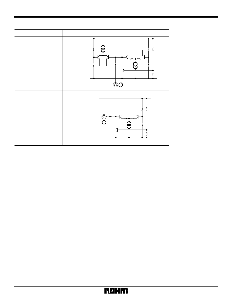
Input / output circuits
Pin name
Pin No.
Equivalent circuit
ECHO LEVEL
CTRL
4
LOOP GAIN
CTRL
6
Note: The BA7725FS is mounted on a 20-pin SSOP-A package with a different pin number than the BA7725S.
On the BA7725FS, the ECHO LEVEL CTRL pin is pin 3, and the LOOP GAIN CTRL pin is pin 5.
4
6
5
Multimedia ICs
BA7725S / BA7725FS
∑
Electrical characteristics (unless otherwise noted, Ta = 25∞C, Vcc = 9V)
Parameter
Symbol
Min.
Typ.
Max.
Unit
Conditions
Supply current
I
CC
4.3
5.7
7.6
mA
No input
Line through output level
V
OLL
≠ 9.0
≠ 8.0
≠ 7.0
dBV
V
IN
= ≠ 26.0dBV
Line through output distortion
THD
LL
--
0.15
0.5
%
Line through maximum output level
V
OML
+ 5.0
+ 7.2
--
dBV
Line through noise level
V
ONL
--
≠ 92
≠ 77
dBV
Microphone through output level
V
OML
≠ 10.5
≠ 8.5
≠ 6.5
dBV
V
IN
= ≠ 52dBV
Microphone through output distortion
THD
ML
--
0.2
0.5
%
Microphone through input conversion noise
V
ONM
--
≠ 114
≠ 104
dBV
Input shorted
Microphone through crosstalk
CT
ML
--
≠ 91
≠ 75
dBV
Compress output level
V
OMC
≠ 6.5
≠ 4.5
≠ 2.5
dBV
V
IN
= ≠ 52dBV
Compress output distortion
THD
MC
--
0.5
2.0
%
Compress noise level
V
ONC
--
≠ 55
≠ 45
dBV
Compress characteristics
CMP
--
≠ 11.0
--
dB
V
ODL1
≠ 11.7
≠ 9.7
--
dBV
V
IN
= ≠ 5.0dBV, V
4
= 9.0V
Expand output distortion
THD
DL
--
0.25
2.0
%
Expand characteristic
EXP
--
≠ 19.5
--
dB
V
ODL2
--
≠ 54
≠ 44
dB
V
ODC1
≠ 7.5
≠ 5.5
--
dBV
V
IN
= ≠ 5.0dBV, V
6
= 9.0V
V
ODC2
--
≠ 42
≠ 32
dBV
MIC OFF holding voltage
V
4OFF
0.0
--
--
--
1.0
V
MIC ON holding voltage
V
4ON
2.0
--
9.0
V
V
IN
= ≠ 42dBV
≠ 62dBV
Output level differential
Expand output level 1
Expand output level 2
V
IN
= 0dBV
≠ 10.0dBV
Output level differential
V
IN
= ≠ 5.0dBV,
Output level differential relative to Vo
DL1
V
IN
= ≠ 5.0dBV,
Output level differential relative to Vo
DC1
Loop output level 1
Loop output level 2
LINE THROUGH
INPUT : LINE IN, OUTPUT : LINE OUT
MIC THROUGH
INPUT : MIC AMP IN, OUTPUT : LINE OUT
COMPRESS
INPUT : MIC AMP IN, OUTPUT : CMP BF OUT
EXPAND
INPUT : DLY BF IN, OUTPUT : LINE OUT
Loop
INPUT : DLY BF IN, OUTPUT : CMP BF OUT
Mode holding voltage
Unless otherwise noted, V4 = 9.0V (MIC ON), V6 = 9.0V (Max. LOOP GAIN)
1 BW = 0.4-30kHz
2 DIN AUDIO
V
6
= 2.0V (VR = Min. time)
V
4
= 2.0V (VR = Min. time)
V
IN
= ≠ 26.0dBV, MIC OFF,
1
MIC OFF, Rg = 600
,
2
V
IN
= ≠ 52dBV,
1
V
IN
= ≠ 44dBV, MIC OFF,
2
V
IN
= ≠ 52dBV,
1
Rg = 600
,
2
V
IN
= ≠ 5.0dBV, V
4
= 9.0V,
1
THD = 1%,
1