SLA-360 / SLA-370 Series
LED lamps
High bright circular LED lamps
(
3, 3.1mm)
SLA-360 / SLA-370 Series
The SLA-360 and SLA-370 series are high luminance LEDs which give you a choice of narrow to wide viewing angles.
One red type and one green type are available in two packages for a total of four different types, and they are suitable for
use in a wide variety of applications.
!
!
!
!
Features
1) Very bright.
2) Ideal for outdoor and semi-outdoor
applications.
3) High reliability.
!
!
!
!
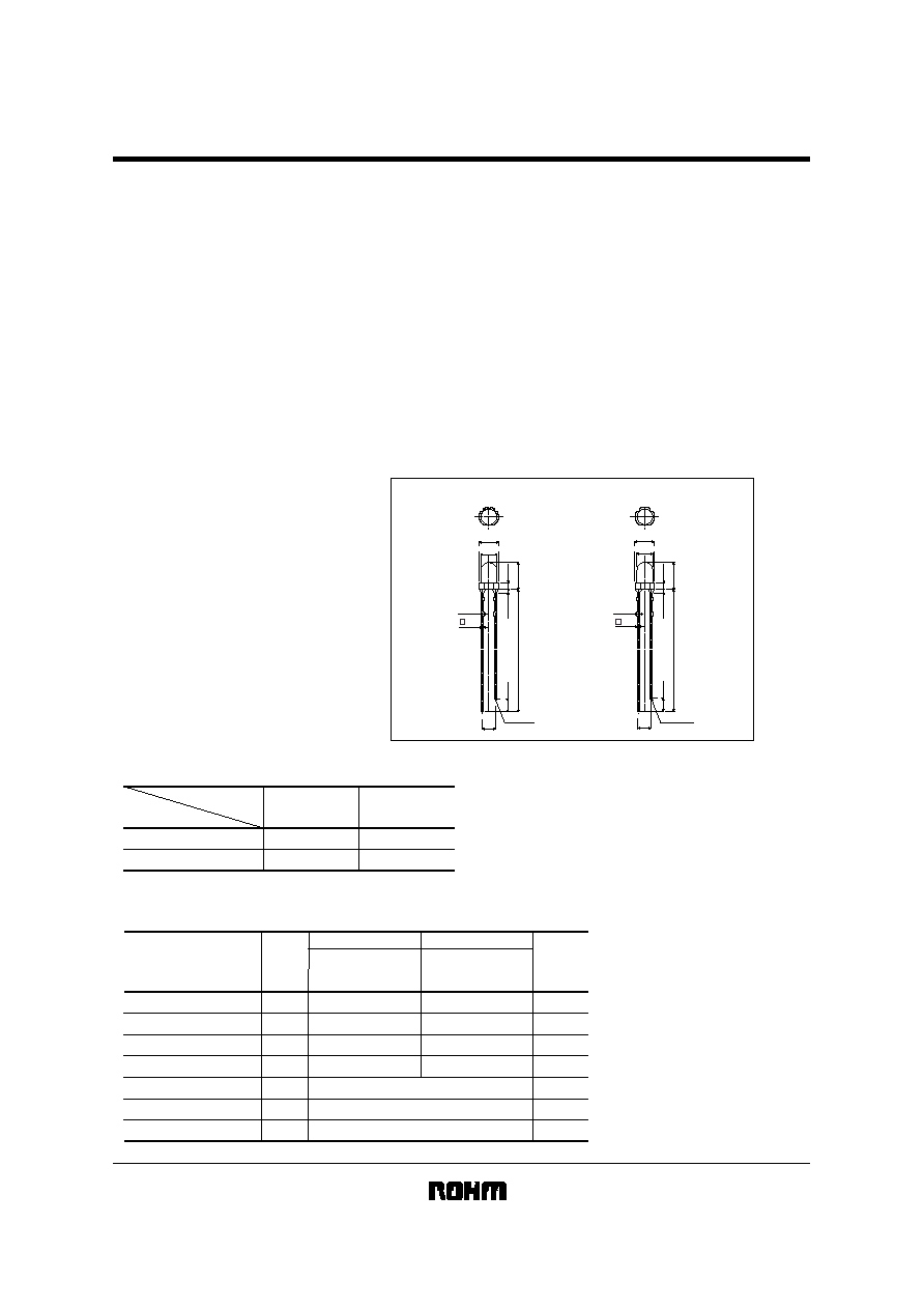
External dimensions (Units : mm)
CATHODE
3.8
±
0.3
24.0Min.
5.2
±
0.3
1.0Max.
2.5
±
1.0
0.4
3.1
±
0.2
(1.3)
(2.5)
(2.5)
CATHODE
3.8
±
0.3
24.0Min.
5.2
±
0.3
1.0Max.
2.5
±
1.0
0.4
3.0
±
0.2
(1.3)
4
-
0.5
4
-
0.5
SLA-370
SLA-360
!
!
!
!
Selection guide
Emitting color
Lens
Medium viewing type
Wide viewing type
SLA-370LT3F
SLA-360LT3F
SLA-370MT3F
SLA-360MT3F
Single-hetero
GaAlAs (red)
GaP (green)
!
!
!
!
Absolute maximum ratings (Ta = 25
°C)
Power dissipation
Forward current
Peak forward current
Reverse voltage
Operating temperature
Storage temperature
Soldering temperature
260
°
C 5 seconds maximum
Parameter
Symbol
SLA-360LT3F
SLA-370LT3F
SLA-360MT3F
SLA-370MT3F
P
D
I
F
I
FP
V
R
Topr
Tstg
-
Unit
mW
mA
mA
V
°
C
°
C
-
Red
Green
-
25~
+
85
-
30~
+
100
100
50
75
4
75
25
60
4
SLA-360 / SLA-370 Series
LED lamps
!
!
!
!
Electrical and optical characteristics (Ta = 25
°C)
Symbol
Unit
Parameter
Red
2
1/2
-
nm
P
-
nm
I
R
-
µ
A
V
F
Conditions
I
F
=
20mA
I
F
=
20mA
V
R
=
4V
I
F
=
20mA
-
Min.
25
660
-
1.75
Typ.
-
-
100
2.5
Max.
Green
-
-
-
-
Min.
40
563
-
2.2
Typ.
-
-
10
3.0
Max.
deg
40
40
-
-
25
25
-
-
SLA-360
SLA-370
V
Viewing angle
Spectral line half width
Peak wavelength
Reverse current
Forward voltage
!
!
!
!
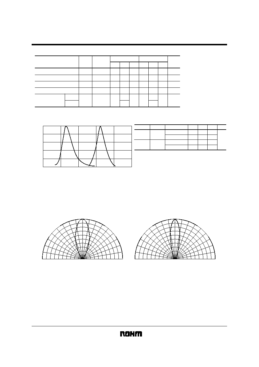
Luminous intensity vs. wavelength
1.0
0.8
0.6
0.4
0.2
0
500
550
600
650
700
750
Axial Luminous Intensity
Wavelength :
P
(nm)
Fig.1
Green
Red
!
!
!
!
Luminous intensity
Unit
Color
Green
Red
P
Type
SLA-360LT3F
SLA-370LT3F
SLA-360MT3F
SLA-370MT3F
660
Min.
Typ.
Max.
-
mcd
-
563
-
-
30
42
42
42
68
100
100
100
Note : 1. Measured at I
F
=20mA
2. The specification is subject to be without notice.
We would like you to refer to the latest specification in use.
!
!
!
!
Directional pattern
ANGLE (
°
)
RELATIVE LUMINOUS INTENSITY
(%)
0
50
100
50
100
0
10
10
20
20
30
40
50
60
70
80
90
30
40
50
60
70
80
90
Fig.2 SLA-360 Directional patterm
ANGLE (
°
)
RELATIVE LUMINOUS INTENSITY
(%)
0
50
100
50
100
0
10
10
20
20
30
40
50
60
70
80
90
30
40
50
60
70
80
90
Fig.3 SLA-370 Directional patterm
SLA-360 / SLA-370 Series
LED lamps
!
!
!
!
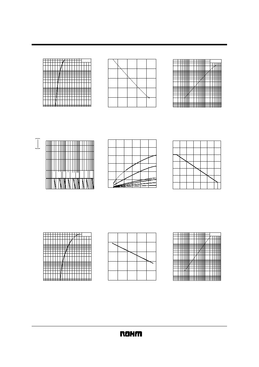
Electrical characteristic curves 1 (red)
20
10
5.0
2.0
1.0
0.5
0.2
0.1
1.5
1.0
2.0
2.5
3.0
50
FORWARD VOLTAGE : V
F
(V)
FORWARD CURRENT : I
F
(
mA
)
Ta=25
°
C
Fig.4 Forward current vs.
forward voltage
1.4
1.2
1.0
0.8
0.6
0.4
-
20
0
20
40
60
80
RELATIVE LUMINOUS INTENSITY
CASE TEMPERATURE : Tc
(°C)
Fig.5 Luminous intensity vs.
case temperature
2
1
0.5
0.2
0.1
0.05
0.02
0.01
0.1 0.2
0.5
1
2
5
10 20
50 100
5
FORWARD CURRENT : I
F
(mA)
RELATIVE LUMINOUS INTENSITY
Ta=25°C
Fig.6 Luminous intensity vs.
forward current
1
2
1.5
3
4
5
6
10
5
20
50
10
3
10
2
10
4
RATIO of MAXIMUM TOLERABLE PEAK CURRENT
to MAXIMUM TOLERABLE DC CURRENT
I
F
peak
M
ax.
I
F
M
ax.
PULSE DURATION : Tw
(
µ
s)
50kHz
20kHz
10kHz
5kHz
2kHz
1kHz
500kHz
200kHz
100kHz
Fig.7 Maximum tolerable peak current
vs. pulse duration
3.0
2.5
2.0
1.5
1.0
0.5
0
0
10
20
30
40
50
60
RELATIVE LUMINOUS INTENSITY
PEAK FORWARD CURRENT : I
F
peak
(mA)
15%
20%
10%
5%
f=1kHz
DC
DF=50%
Fig.8 Luminous intensity
vs. peak forward current
40
30
20
10
0
20
30
40
50
60
70
80
90
60
50
70
AMBIENT TEMPERATURE : Ta
(°C)
MAXIMUM FORWARD CURRENT : I
F
M
ax.
(mA)
Fig.9 Maximum forward current
vs. ambient temperature
(Derating)
!
!
!
!
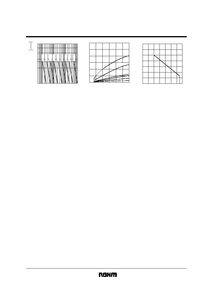
Electrical characteristic curves 2 (green)
20
10
5.0
2.0
1.0
0.5
0.2
0.1
1.5
1.0
2.0
2.5
3.0
50
FORWARD VOLTAGE : V
F
(V)
FORWARD CURRENT : I
F
(mA)
Ta=25°C
Fig.10 Forward current vs.
forward voltage
1.4
1.2
1.0
0.8
0.6
0.4
-
20
0
20
40
60
80
RELATIVE LUMINOUS INTENSITY
CASE TEMPERATURE : T
c
(°C)
Fig.11 Luminous intensity vs.
case temperature
Ta=25°C
2
1
0.5
0.2
0.1
0.05
0.02
0.01
0.1 0.2
0.5
1
2
5
10 20
50 100
5
FORWARD CURRENT : I
F
(
mA)
RELATIVE LUMINOUS INTENSITY
Fig.12 Luminous intensity vs.
forward current
SLA-360 / SLA-370 Series
LED lamps
1
2
2.4
3
4
5
6
RATIO of MAXIMUM TOLERABLE PEAK CURRENT
to MAXIMUM TOLERABLE DC CURRENT
I
F
peak
M
ax.
I
F
M
ax.
PULSE DURATION : Tw
(
µ
s)
10
5
20
50 10
2
10
3
10
4
50kHz
20kHz
10kHz
5kHz
2kHz
1kHz
500Hz
200Hz
100Hz
Fig.13 Maximum tolerable peak current
vs. pulse duration
3.0
2.5
2.0
1.5
1.0
0.5
0
0
10
20
30
40
50
60
RELATIVE LUMINOUS INTENSITY
PEAK FORWARD CURRENT : I
F
peak
(mA)
15%
20%
10%
5%
f=1kHz
DC
DF=50%
Fig.8 Luminous intensity
vs. peak forward current
20
10
0
20
30
40
50
60
70
80
90
30
AMBIENT TEMPERATURE : Ta
(°C)
MAXIMUM FORWARD CURRENT : I
F
M
ax
(mA)
Fig.15 Maximum forward current
vs. ambient temperature
(Derating)