+ FEATURES
+
Functionally compatible with the SA9602E with reduced
external components
+
Uni-directional power and energy measurement
+
Meets the IEC 521/1036 Specification requirements for
Class 1 AC Watt hour meters
+
Protected against ESD
sames
sames
Single Phase Uni-directional Power / Energy
Metering IC with Instantaneous Pulse Output
SA2002E
1/10
SA2002E (REV. 5)
17-08-00
+
Total power consumption rating below 25mW
+
Adaptable to different types of current sensors
+
Operates over a wide temperature range
+
Precision voltage reference on-chip
+
Precision oscillator on-chip
DESCRIPTION
The SAMES SA2002E is an enhancement of the SA9602E, as
the circuit contains the oscillator on chip.
The SAMES SA2002E single phase uni-directional
power/energy metering integrated circuit generates a pulse
rate output with a frequency proportional to the power
consumption.
The SA2002E performs a calculation for active power. The
method of calculation takes the power factor into account.
Energy consumption can be determined by the power
measurement being integrated over time.
This innovative universal single-phase power/energy metering
integrated circuit is ideally suited for energy calculations in
applications such as residential municipal metering and factory
energy metering and control.
The SA2002E integrated circuit is available in 8, 14 and 20 pin
dual-in-line plastic (DIP) as well as 16 and 20 pin small outline
(SOIC) package types.
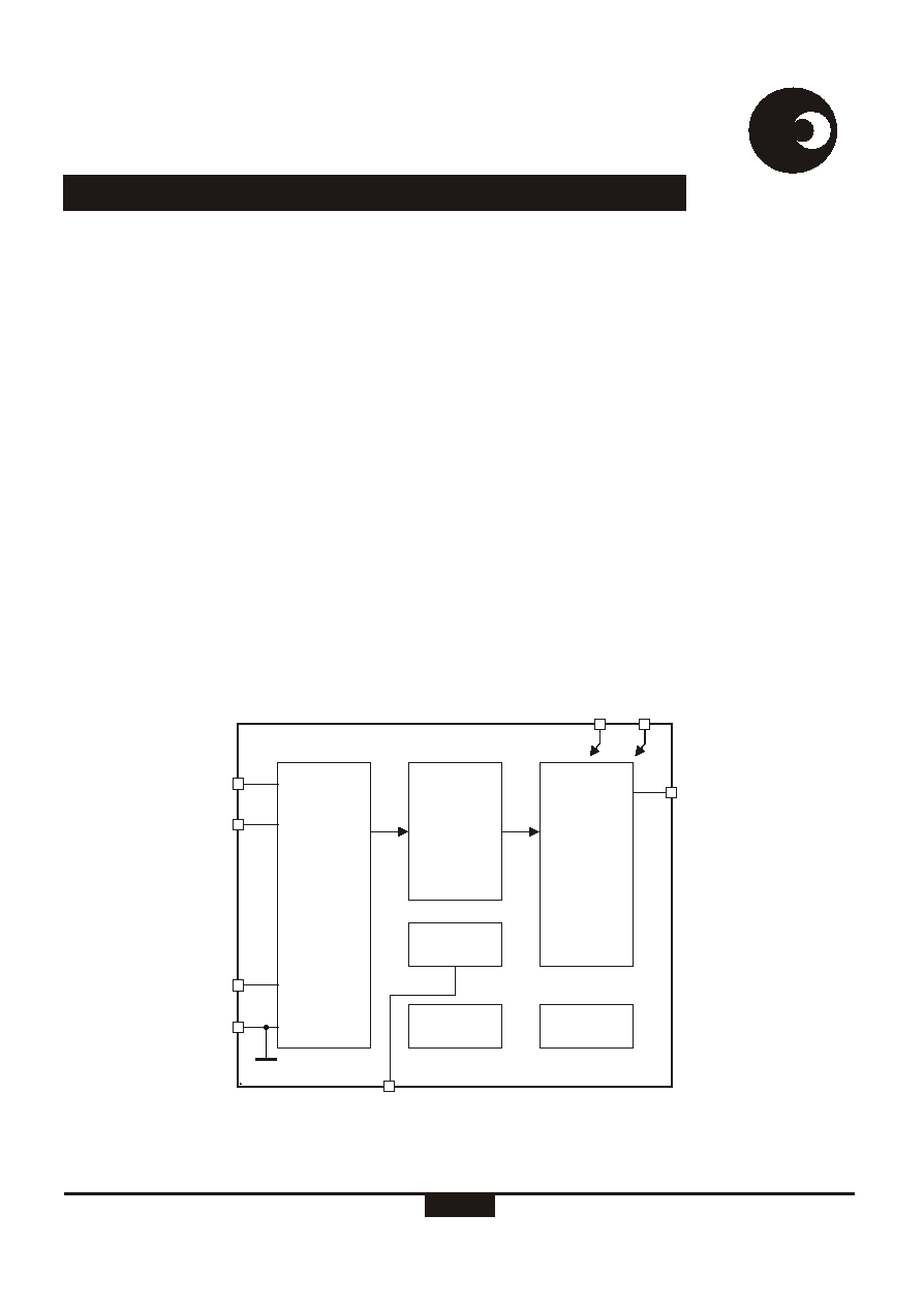
Figure 1: Block diagram
IIP
IIN
IVP
GND
VREF
DR-01586
POWER
TO
FREQUENCY
FOUT
V
DD
V
SS
POWER
INTEGRATOR
ANALOG
SIGNAL
PROCESSING
TIMING
OSC
VOLTAGE
REF.
ABSOLUTE MAXIMUM RATINGS*
Supply Voltage
V -V
-0.3
6.0
V
DD
SS
Current on any pin
I
-150
+150
mA
PIN
Storage Temperature
T
-40
+125
�C
STG
Operating Temperature
T
-25
+85
�C
O
*Stresses above those listed under "Absolute Maximum Ratings" may cause permanent damage to the device. This is a stress
rating only. Functional operation of the device at these or any other condition above those indicated in the operational sections of
this specification, is not implied. Exposure to Absolute Maximum Ratings for extended periods may affect device reliability.
Parameter
Symbol
Min
Max
Unit
sames
sames
SA2002E
2/10
3
http://www.sames.co.za
ELECTRICAL CHARACTERISTICS
#
(V = 2.5V, V = -2.5V, over the temperature range -10�C to +70�C , unless otherwise specified.)
DD
SS
Operating temp. Range
Supply Voltage: Positive
Current Sensor Inputs (Diffferential)
Input Current Range
Voltage Sensor Input (Asymmetrical)
Input Current Range
Pin FOUT
Output High Voltage
Output Low Voltage
�C
V
�A
�A
V
V
T
O
V
DD
I
II
I
IV
V
OL
V
OH
-25
-25
-25
2.25
V -1
DD
V +1
SS
+25
+25
+85
2.75
Peak value
Peak value
Condition
Unit
Max
Typ
Min
Symbol
Parameter
Supply Voltage: Negative
V
V
SS
-2.75
-2.25
Supply Current: Positive
I
DD
5
3
mA
Supply Current: Negative
I
SS
5
3
mA
With R = 24kW
connected to V
SS
Reference to V
SS
Pin VREF
Ref. Current
Ref. Voltage
�A
V
45
1.1
55
1.3
-I
R
V
R
50
# Extended Operating Temperature Range available on request.
Pulse Rate FOUT
At rated input conditions
Specified linearity
Min and Max frequency
Hz
Hz
Hz
1600
3000
1360
5
0
f
p

3/10
sames
sames
SA2002E
http://www.sames.co.za
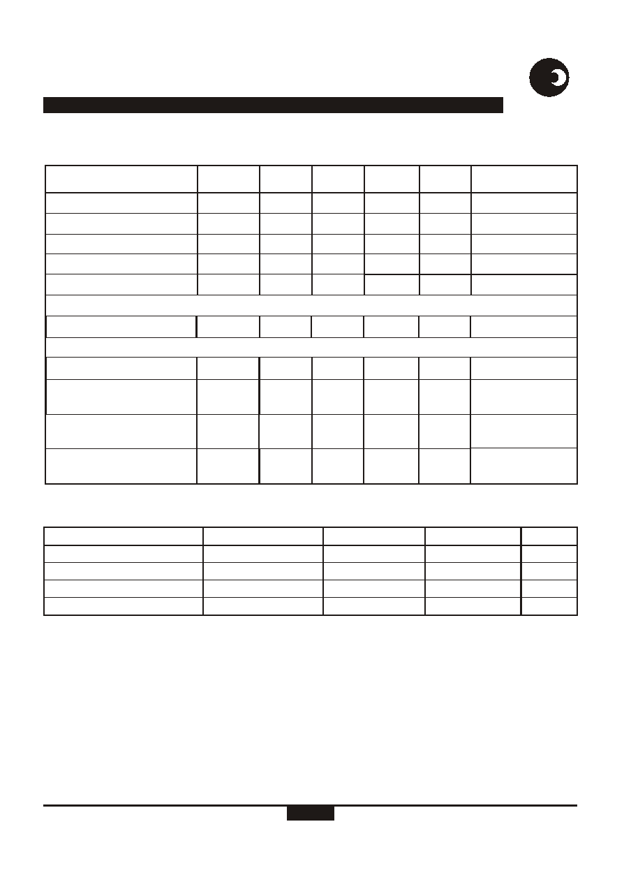
PIN DESCRIPTION
8
Pin
14
Pin
16
Pin
20
Pin
Designation
Description
8
14
16
20
GND
Analog Ground. The voltage to this pin should be mid-way
between V and V .
DD
SS
4
5
5
8
V
DD
Positive supply voltage. The voltage to this pin is typically +2.5V
if a shunt resistor is used for current sensing or in the case of a
current transformer a +5V supply can be applied.
6
10
12
14
V
SS
Negative supply voltage. The voltage to this pin is typically -2.5V
if a shunt resistor is used for current sensing or in the case of a
current transformer a 0V supply can be applied.
7
13
15
19
IVP
Analog Input for Voltage. The current into the A/D converter
should be set at 14�A
at nominal mains voltage. The
RMS
voltage sense input saturates at an input current of �25�A peak.
1, 2
1, 2
1, 2
1, 2
IIN, IIP
Inputs for current sensor. The shunt resistor voltage from each
channel is converted to a current of 16�A
at rated conditions.
RMS
The current sense input saturates at an input current of �25�A
peak.
3
3
3
3
VREF
This pin provides the connection for the reference current setting
resistor. A 24kW resistor connected to V set the optimum
SS
operating condition.
5
8
6
12
FOUT
Pulse rate output. Refer to pulse output format for a description
of the pulse rate.
4
4
4
6
7
5
7
8
6
9
9
7
11
9
12
11
10
13
11
14
13
15
16
17
18
TP1
TP2
TP3
TP4
TP5
TP6
TP7
TP8
TP9
TP10
TP11
TP12
Leave pins unconnected.
10
4/10
sames
sames
SA2002E
http://www.sames.co.za
Figure 2: Pin connections: Package: DIP-8
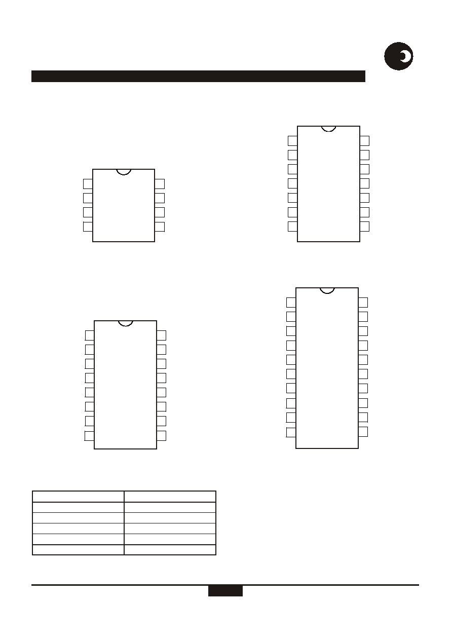
Figure 4: Pin connections: Package: SOIC-16
Figure 3: Pin connections: Package: DIP-14
Figure 5: Pin connections: Package: DIP-20, SOIC-20
Part Number
SA2002EPA
SA2002EPA
SA2002EPA
SA2002ESA
SA2002ESA
Package
DIP-8
DIP-14
DIP-20
SOIC-16
SOIC-20
ORDERING INFORMATION
1
IIN
GND
IIP
IVP
TP4
TP6
FOUT
VREF
TP1
V
DD
TP2
TP3
TP5
V
SS
2
3
4
5
6
9
8
7
10
11
12
13
14
dr-01485
DR-01486
1
IIN
GND
IIP
IVP
TP6
TP8
V
SS
VREF
TP1
TP3
FOUT
TP2
V
DD
TP7
TP5
TP4
2
3
4
5
6
11
10
9
8
7
12
13
14
15
16
1
IIN
GND
IIP
IVP
V
SS
VREF
V
DD
FOUT
2
3
4
5
6
7
8
dr-01484
DR-01483
1
IIN
GND
IIP
IVP
TP9
TP12
V
SS
VREF
TP1
TP2
TP3
TP4
V
DD
TP11
TP10
TP8
FOUT
TP5
TP6
TP7
2
3
4
5
6
15
14
13
12
11
10
9
8
7
16
17
18
19
20

5/10
sames
sames
SA2002E
http://www.sames.co.za
FUNCTIONAL DESCRIPTION
The SA2002E is a CMOS mixed signal Analog/Digital
integrated circuit, which performs power/energy calculations
across a power range of 1000:1, to an overall accuracy of
better than Class 1.
The integrated circuit includes all the required functions for 1-
phase power and energy measurement such as two
oversampling A/D converters for the voltage and current sense
inputs, power calculation and energy integration. Internal
offsets are eliminated through the use of cancellation
procedures. The SA2002E generates pulses, the frequency of
which is proportional to the measured power consumption.
One frequency output (FOUT) is available. The pulse rate
follows the instantaneous power consumption measured.
POWER CALCULATION
In the application circuit (figure 6), the voltage drop across the
shunt will be between 0 and 16mV
(0 to 80A through a shunt
RMS
resistor of 200�W) The voltage is converted to a current of
between 0 and 16uA
, by means of resistors R1 and R2. The
RMS
current sense inputs saturates at an input current of �25�A
peak.
For the voltage sensor input, the mains voltage (230VAC) is
divided down through a divider (R3, R4 and P1) to 14V
. The
RMS
current into the A/D converter input is set at 14�A
at nominal
RMS
mains voltage, via resistor R5 (1MW). P1 may be varied for
calibration purposes.
In this configuration, with a mains voltage of 230V and a
current of 80A, the output frequency measured on the FOUT
pin is 1360Hz. In this case one pulse on FOUT correspond to
an energy consumption of 18.4kW/1360Hz = 13.53Ws.
ANALOG INPUT CONFIGURATION
The input circuitry of the current and voltage sensor inputs is
illustrated in figure 7. These inputs are protected against
electrostatic discharge through clamping diodes. The
feedback loops from the outputs of the amplifiers A and A
I
V
generate virtual shorts on the signal inputs. Exact duplications
of the input currents are generated for the analog signal
processing circuitry.
Figure 6: Application circuit
Figure 7: Internal analog input configuration
GND
VDD
DR-01148
VOLTA GE
SENSOR
INPUT
IVP
SS
V
IIN
IIP
CURRENT
SENSOR
INPUTS
SS
V
SS
V
VDD
DD
V
A
V
A
I
DR-01584
R3
VDD
VREF
IIP
IIN
GND
IVP
VSS
FOUT
U1
SA2002E
R4
R5
R1
R2
R6
L
N
L
N
RSH
P1
GND
GND
VSS
VDD
GND
Supply
VDD
VSS
Pulse output