
Page 1
The SM5221-001/002 is an infrared remote
c o n t r o l e n c o d e r L S I u t i l i z i n g C M O S
t e c h n o l o g y . T h e t r a n s m i s s i o n c o d e
consists of "leader pulse", "16 bit customer
code", and "16 bit data code". Using
Micro-processors for decoder,
various
applications
can
be realized.
PIN ASSIGNMENTS (TOP VIEW)
1
2
3
4
5
6
7
8
9
10
20
19
18
17
16
15
14
13
12
11
KI0
KI1
KI2
KI3
Dout
V
DD
SEL
OSCO
OSCI
V
SS
CODE
KI/O0
KI/O1
KI/O2
KI/O3
KI/O4
KI/O5
KI/O6
KI/O7
LED
20 PIN DIP IN 300MIL
20 PIN SOP IN 300MIL
GENERAL DESCRIPTION
APPLICATIONS
* Audio Remote Control
* Video Remote Control
* Consumer Product Remote Control
FEATURES
* Low voltage operation ...... VDD=2.0 to 3.3V
* Low power consumption ...... IDD < 1
A at
standby mode
* 32 function keys and 3 double action keys
* 64 + 6 function codes are available.
(Using SEL terminal)
* 65536 customer codes can be selected.
(Using external R, Diode-SM5024A or internal
MASK ROM-SM5024B)
* 20pin SOP or DIP
1
2
3
4
5
6
7
8
9
10
20
19
18
17
16
15
14
13
12
11
KI0
KI1
KI2
KI3
Dout
V
DD
SEL
OSCO
OSCI
V
SS
CODE
KI/O0
KI/O1
KI/O2
KI/O3
KI/O4
KI/O5
KI/O6
KI/O7
LED
V.2.0 Mar 8,2002
SM5221-001/002
32 KEYS ENCODER
S
AM
H
OP
Microelectronics Corp.

Page 2
20
8
9
6
10
13
12
5
7
11
18
17
16
15
14
No.
1
2
3
4
19
PIN DESCRIPTION
No.
1
2
3
4
5
6
7
8
9
10
11
12
13
14
Pin Name I / O
Function
I
I
I
I
POWER
O
I
O
POWER
I
KI0
KI1
KI2
KI3
DOUT
VDD
SEL
OSCO
OSCI
VSS
Scan Key Input 0
With Pull Low
Scan Key Input 1
With Pull Low
Scan Key Input 2
With Pull Low
Scan Key Input 3
With Pull Low
Remote Output
Data Select
Oscillator Output
Oscillator Input
15
16
17
18
19
20
O
I / O
I / O
I / O
LED
KI/O7
KI/O6
KI/O5
KI/O4
KI/O3
KI/O2
KI/O1
KI/O0
CODE
Indicator For
Tramsmission
Key Scan 7
Key Scan 6
Key Scan 5
Key Scan 4
Key Scan 1
Key Scan 2
Key Scan 3
Key Scan 0
Customer Code
Select Input
Pin Name
I / O
Function
I
I
I
I
O
I
I
KI0
KI1
KI2
KI3
CODE
SEL
Remote Output
Data Select
Oscillator Output
Oscillator Input
KI/O1
KI/O4
KI/O0
KI/O2
Key Scan 4
Customer Code
Select Input
Indicator For
Tramsmission
Key Scan 6
Key Scan 7
Key Scan 5
I / O
POWER
O
O
POWER
I / O
OSCO
VSS
VDD
OSCI
LED
DOUT
KI/O7
KI/O3
KI/O5
KI/O6
Key Scan 3
Key Scan 1
Key Scan 2
I / O
I / O
I / O
I / O
I / O
I / O
I / O
Postive Power
Supply
Negative Power
Supply (substrate)
Postive Power
Supply
Negative Power
Supply (substrate)
Scan Key Input 0
With Pull Low
Scan Key Input 1
With Pull Low
Scan Key Input 2
With Pull Low
Scan Key Input 3
With Pull Low
Key Scan 0
V.2.0 Mar 8,2002
I / O
I / O
I / O
I / O
I / O
I / O
SM5221-001/002
32 KEYS ENCODER
S
AM
H
OP
Microelectronics Corp.

Page 3
FUNCTION DESCRIPTION
(1) Oscillation
BLOCK DIAGRAM
V.2.0 Mar 8,2002
KEY INPUT/OUTPUT SCAN CIRCUIT
OSC CIRCUIT
KEY INPUT SCAN
CIRCUIT
OUTPUT
CONTROL
CIRCUIT
OSCI
OSCO
DOUT
CODE GENERATION CIRCUIT
TIMING GENERATION & CONTROL
CIRCUIT
V
DD
Vss
CODE
LED
KI/O0 KI/O1 KI/O2 KI/O3 KI/O4 KI/O5 KI/O6 KI/O7
SEL
KI
3
KI
0
KI
1
KI
2
OSCO
C
2
OSCI
C
1
The SM5221-001/002 oscillation circuit is designed for use of a 400 kHz or 500 kHz ceramic
resonator, but there may be mutual influence between variations in the IC and ceramic
resonator resulting in abnormal oscillation. The oscillation circuit starts to operate when a key
is depressed.
SM5221-001/002
32 KEYS ENCODER
S
AM
H
OP
Microelectronics Corp.

(2) Key Scan
(3) Data Code D
7
Control
Page 4
V.2.0 Mar 8,2002
Data code D7 can be controlled by this pin, allowing 64 kinds of data to be transmitted.
D7 is set to "0" by connecting the SEL pin to VDD, and to "1" by connecting the SEL pin to
VSS. As the input of this pin is high-impedance, it must be connected to either VDD or VSS.
A pull-down resistor is inserted
keys are depressed simultaneously, transmission is disabled by the multi-depression
prevention circuit.
When a key is depressed, reading of the custom code and key data code is started, and DOUT
output begins 36 ms later, so that if the key is being depressed during this 36 ms interval one
transmission is performed. If a key is held down for 108 ms or longer, consecutive
transmissions of the leader code only are performed while the key is depressed.
Ex. f OSC = 455 kHz
MIN. 36 ms
Key Input
58.5 to 76.5 ms
108 ms
108 ms
SM5221-001/002
32 KEYS ENCODER
S
AM
H
OP
Microelectronics Corp.
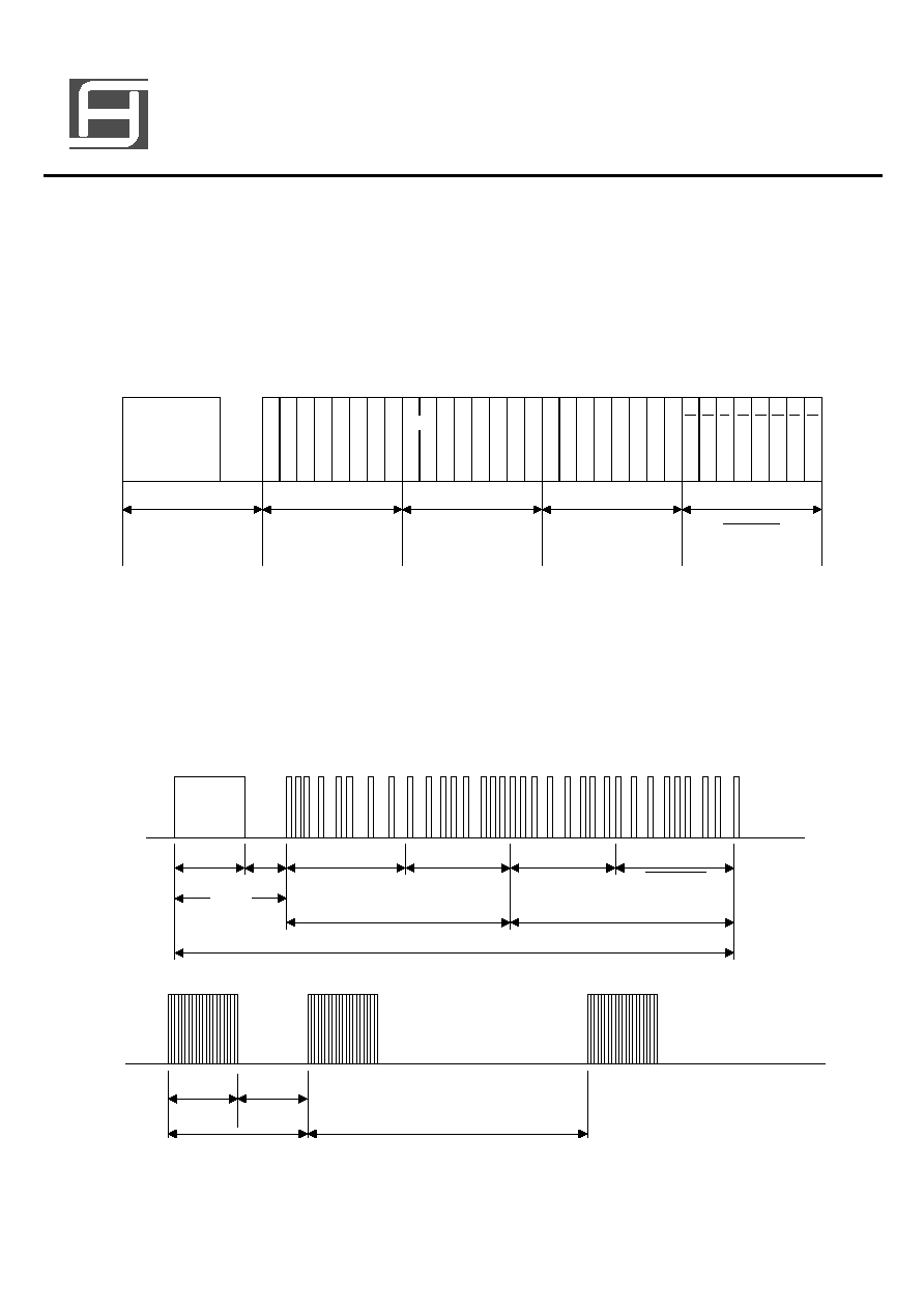
TRANSMISSION CODE
(1) DOUT Output
The transmission code consists of a leader code, 16-bit custom code, and 8-bit data code.
The inverse code of the data code is also sent simultaneously, giving a total configuration
of 32 bits per transmission.
The leader code consists of a 9 ms carrier waveform plus a 4.5 ms OFF waveform, and is
used as the leader for the following code. The code uses the PPM (Pulse Position
Modulation) method, with "1" and "0" differentiated by the time between pulses reference
following diagram. Each code consists of 8 bits, and simultaneous transmission of the
inverse code.
Page 5
V.2.0 Mar 8,2002
DOUT Output Code
C6
C0'
C1 C2
C4
C3
C5
C7
C1' C2' C3' C4' C5' C6' C7' D0 D1 D2 D3 D4 D5 D6 D7 D0 D1 D2 D3 D4 D5 D6 D7
Leader
Code
Custom Code
Custom Code'
Data Code
Data Code
C0
9 ms
4.5 ms
13.5 ms
Leader
Code
Custom Code
8 bits
Custom Code'
8 bits
Data Code
8 bits
Data Code
8 bits
18 ms to 36 ms
58.5 to 76.5 ms
1.125 ms
Bit 0
0.56 ms
2.25 ms
Bit 1
0.56 ms
SM5221-001/002
32 KEYS ENCODER
S
AM
H
OP
Microelectronics Corp.