
RDS DEMODULATOR IC
S1A0905
1
Preliminary
GENERAL DESCRIPTION
THE OUTLINE OF RDS(RADIO DATA SYSTEM)
Since 1988 most European national broadcaststations transmit RDS-
code beside their audio signals. RDS means Radio Data System and
was originally intended to give people in their cars additional informa-
tion about the weather or traffic(jams). But RDS has grown out to one
big channel of information. Radiostations send their name, the time
(with DCF-77 accuracy), their type of music (format) and even more.
The digital data of RDS are multiplexed into an FM radio wave using a
sub-carrier of 57kHz. The transmission rate of RDS data is
1.1875kbit/sec.
The transmission rate of RDS data is 1.1875kbit/sec, and RDS data
are encoded by differential encoding method. Then the encoded RDS data are modulated by BPSK using a clock
of 1.1875kHz. The modulated RDS data is are modulated by carrier suppressed amplitude modulation using a sub-
carrier of 57kHz. And that signal are multiplexed into an FM radio wave.
∑RDS data are obtained by demodulating the received RDS modulation signal in RDS demodulator. First, the RDS
modulation signal is extracted from an FM radio wave using a band pass filter. The BPSK signal is obtained from
extracted RDS modulation signal by a 57kHz carrier recovery circuit. Then the bit rate clock of RDS data is
extracted from the BPSK signal, and the BPSK signal is demodulated using the extracted clock signal. Then the
RDS data are decoded by a differential decoding method using the demodulated BPSK signal.
FEATURES
∑
Low Current
∑
Two Stage Anti-aliasing Filter
∑
8'th 57kHz Switched Capacitor Bandpass Filter
∑
DSB Demodulation (Carrier Recovery)
∑
Clock Recovery Circuit
∑
Biphase Decoder & Differential Decoder
∑
Quality Indication Output for Demodulated Data
ORDERING INFORMATION
DEVICE
PACKAGE
OPERATING TEMP.
S1A0905-S0B0
16-SOP-225
-40
-
+85
16
-
SOP
-
225

S1A0905
RDS DEMODULATOR IC
2
Preliminary
DESCRIPTIONS
The S1A0905 is a RDS demodulator. It recovers the RDS data which is transmitted by FM radio broadcasting. The
device operates in accordance with the EBU(European Broadcasting Union) specifications.
The IC includes a two stage antialiasing filter, a 57kHz switched capacitor bandpass filter, a comparator, a 57kHz
carrier recovery circuit, a bit rate clock recovery circuit, BPSK decoder, differential decoding circuit, and RDS signal
quality output.
BLOCK DIAGRAM
Smoothing filter & Comparator
BPSK
BPSK
Recovered clock
RDS DEMODULATOR
MUX
VREF
VDDA
VSSA
COMP
QUAL(High or Low)
DATAO
CLKO
XOSCO
XOSCI
4.332MHz
20pF
20pF
2'nd Antialiasing Filter
Switched capacitor filter
VSS
+5.0V
VDD
RSTB
TEST
TIN
BIAS
8'th order
SCF
BGR
Oscillator &
Divider
Carrier
Recovery
Clock
Recovery
PLL
1.1875kHz
Biphase
Decoder
Differential
Decoder
RDS DEMODULATOR IC
S1A0905
3
Preliminary
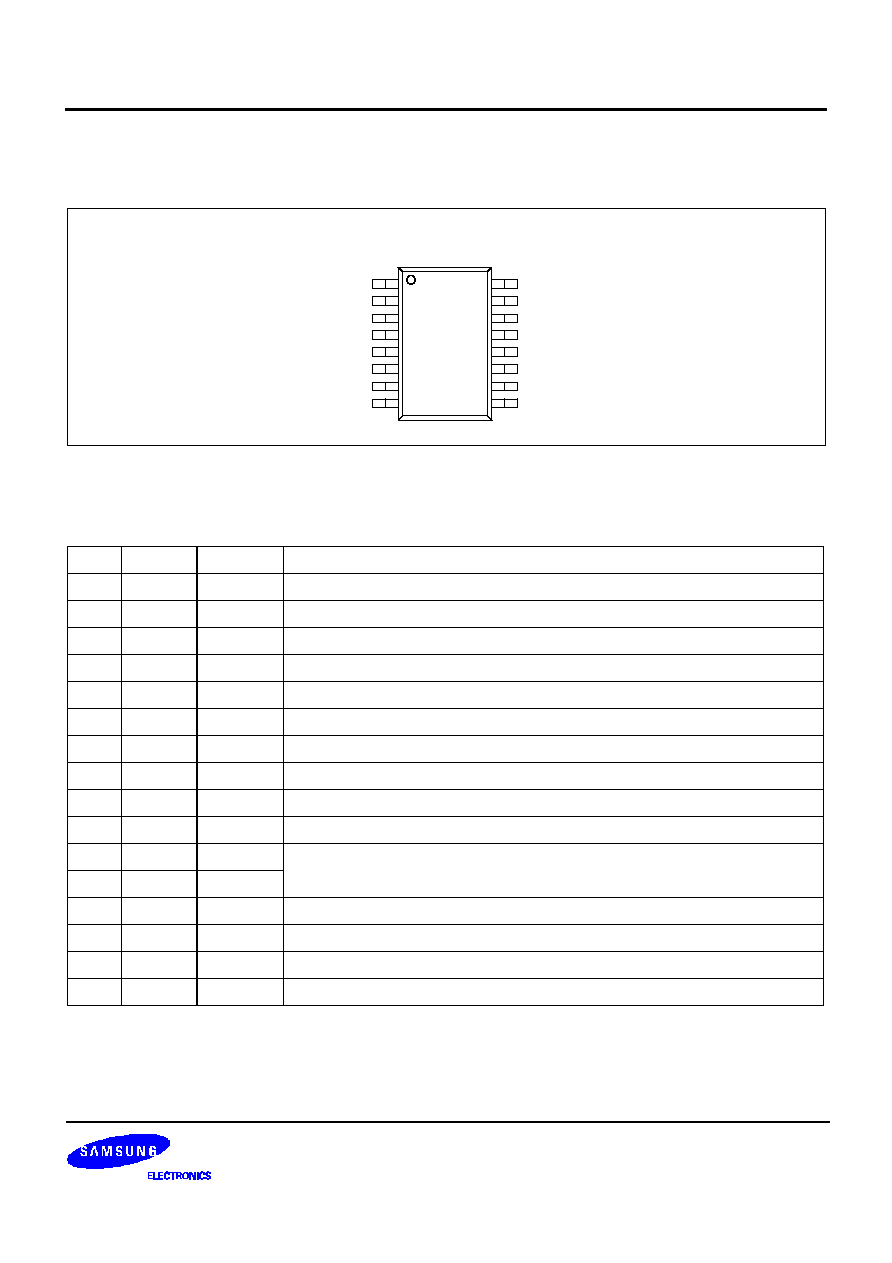
PIN CONFIGURATION
PIN DESCRIPTIONS
I: Input pin, O: Output pin, P: Power pin
Pin
Name
I/O
Description
1
QUAL
O
Output for data quality indication (High = good data Low = bad data)
2
DATAO
O
RDS data output
3
VREF
O
System reference voltage output (2.5V)
4
MUX
I
Composite signal input
5
VDDA
P
Analog power (+5.0V)
6
VSSA
P
7
SGND
P
System ground
8
COMP
O
Bandpass filter output
9
TEST
I
Test enable selecton pin (High = Test mode, Low = Normal mode)
10
TIN
I
Input signal for Test mode (Normally ground or open)
11
VSS
P
Digital power(+5.0V)
12
VDD
P
13
XOSCI
I
Xtal oscillator input
14
XOSCO
O
Xtal oscillator output
15
RSTB
I
Input for system reset (High = active mode, Low = reset mode)
16
CLKO
O
RDS clock output (1187.5Hz)
QUAL
DATAO
VREF
MUX
VDDA
VSSA
SGND
COMP
SEC
S1A0905X01
TEST
TIN
VSS
VDD
XOSCI
XOSCO
RSTB
CLKO
16 SOP
(TOP VIEW)
1
2
3
4
5
6
7
8
16
15
14
13
12
11
10
9

S1A0905
RDS DEMODULATOR IC
4
Preliminary
ELECTRICAL CHARACTERISTICS
Recommended Operating Conditions (Ta = 25
∞
C)
Electrical Characteristics (VDDA = 5.0V, Ta = 25
∞
C, fosc = 4.332MHz)
|
Parameter
Symbol
Min.
Typ.
Max.
Unit
Conditions
Power supply voltage1
VDDA
4.5
5.0
5.5
V
Analog power
Power supply voltage2
VDD
4.5
5.0
5.5
V
Digital power
Parameter
Symbol
Min.
Typ.
Max.
Unit
Conditions
Operating current
Isum
-
3.5
4.0
mA
i(VDDA)+i(VDD)
Reference voltage
VREF
2.4
2.5
2.6
V
Ouput high level
Voh
VDDA-1.0
VDDA-0.3
-
V
CLKO,DATAO,QUAL
Output low level
Vol
-
0.2
1.0
V
CLKO,DATAO,QUAL
<Filter block>
Center frequency
Fc
56.5
57
57.5
kHz
Gain
GA
23
26
29
dB
Fc=57kHz, MUXFILO
Attenuation1
ATT1
-18
-22
-
dB
57.0kHz4kHz
Attenuation2
ATT2
-65
-80
-
dB
38kHz
Attenuation3
ATT3
-35
-50
-
dB
67kHz
S/N ratio
SN
30
40
-
dB
57kHz Vin=3mVrms
Input level
Vin
1
-
500
mVrms
<Demodulator block>
RDS detecter sensitivity
SRDS
-
0.5
1.0
mVrms
RDS input level
VRDS
-
-
300
mVrms
DATA rate
DRATE
-
1187.5
-
Hz
Clock transient vs. DATA
CT
-
4.3
-
us
Lockup time(RDS)
TL
-
100
200
ms
<Oscillator block>
XTAL frequency
Fosc
-
4.332
-
MHz
Clock input high level
Xosci
4.0
-
-
V
Clock input low level
Xosco
-
-
1.0
V
Output Amplitude
Xosc
-
4.5
-
Vpp
Load capacitance
CL
-
20
-
pF

RDS DEMODULATOR IC
S1A0905
5
Preliminary
TEST APPLICATION
Analog ground
Analog power
Digital power
Digital ground
:Input & Monitor Pin
:Switch
:Crystal oscillator
S1A0905X01
4.332MHz
O1
5V
I2
SW2
O6
5V
QUAL DATAO VREF MUX VDDA VSSA SGND COMP
TEST
TIN
VSS
VDD
XOSCI
XOSCO
RSTB
CLKO
20pF
20pF
I3
O7
A
B
SW3
A
B
SW4
SW5
16
15
14
13
12
11
10
9
1
2
3
4
5
6
7
8
A
B
A
B
O2
O3
O4
0.01uF
10uF
I1
10nF
SW1
O5
5V
14pF
0.1uF
10uF
0.1uF
10uF
A
B
A
B
*1: Digital power supply and Analog power supply are separated in the IC
*2: It must have VDD (Digital power supply) of a sufficiently low impedence

S1A0905
RDS DEMODULATOR IC
6
Preliminary
NOTES