1
www.semtech.com
EZ1580/EZ1581
EZ1582/EZ1583
Dual Input Low Dropout Regulator
POWER MANAGEMENT
Revision 1, January 2001
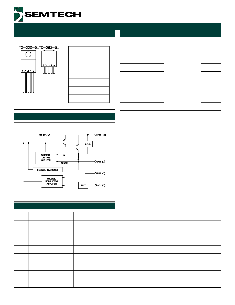
The EZ158X family of high performance positive voltage
regulators are designed for use in applications requiring
very low dropout voltage at up to 7, 5, 3 and 1.5 amps.
Capable of supplying up to 2.8V on boards where both
5V and 3.3V supplies are available, the superior dropout
characteristics of the EZ158X result in reduced heat
dissipation compared to regular LDOs. This allows for
heatsink size reduction or elimination. Additionally, the
EZ158X provides excellent regulation over variations in
line, load and temperature. Remote sense operation
allows compensating for trace, connector and other
resistive losses.
Outstanding features include very low dropout
performance at rated current, fast transient response,
remote sense, internal current limiting, thermal shutdown
and safe operating area protection of the output device.
The EZ158X is a five terminal adjustable voltage regula-
tor available in the popular 5 pin TO-220 and TO-263
plastic packages.
u
540mV dropout @ 7A in dual supply mode
(EZ1580)
u
Remote sense operation
u
Fast transient response
u
0.5% initial accuracy
u
Line regulation typically 0.08%
u
Load regulation typically 0.08%
u
5 Pin TO-220 and TO-263 packages
u
Microprocessor supplies
u
Split plane microprocessor supplies
u
Advanced graphics cards
u
Sound cards
u
Low voltage logic supplies
u
Switching power supply post regulation
Notes:
(1) Capacitor values are for reference only. Good quality, low ESR tantalum or aluminum electrolytic capacitors
should be used. Increasing the value of the output capacitor will improve the overall transient response.
(2) If the same voltage is input to both PWR and CTL, then the dropout voltage will become 1.3V maximum.
(3) A small (~0.033µF) capacitor can be used to bypass the ADJ pin to improve transient response, if needed.
2.5V OUT
3.3V POWER IN
5V CONTROL IN
GROUND
GROUND
C2
10uF
C1
33uF
C3
68uF
R1
124
R2
124
U1
EZ158XCX
4
3
2
1
5
CTL
OUT
ADJ
SNS
PWR
VREF
2
R
I
1
R
2
R
1
V
V
ADJ
REF
OUT
∑
+
+
=
GROUND
GROUND
3.3V POWER IN
2.5V OUT
5V CONTROL IN
C2
10uF
U1
EZ158XCX-2.5
4
3
2
1
5
CTL
OUT
GND
SNS
PWR
C3
68uF
C1
33uF
GROUND
1.5V OUT
3.3V CONTROL IN
2.5V POWER IN
GROUND
C2
10uF
C3
100uF
C1
47uF
U1
EZ158XCX-1.5
4
3
2
1
5
CTL
OUT
GND
SNS
PWR
Adjustable Output Parts
(3)
Fixed Output Parts
Description
Features
Applications
Typical Application Circuits

3
„ 2001 Semtech Corp.
www.semtech.com
POWER MANAGEMENT
EZ1580/EZ1581
EZ1582/EZ1583
Electrical Characteristics (Cont.)
(7)
Unless specified: V
OUT
= V
SNS
, V
ADJ
= 0V, C
CTL
= C
PWR
= C
OUT
= 10µF. Values in bold apply over full operating temperature range.
r
e
t
e
m
a
r
a
P
l
o
b
m
y
S
s
n
o
it
i
d
n
o
C
t
s
e
T
n
i
M
p
y
T
x
a
M
s
ti
n
U
t
n
e
rr
u
C
n
i
P
l
o
rt
n
o
C
)
3
(
3
8
5
1
Z
E
I
L
T
C
V
R
W
P
V
=
T
U
O
V
,
V
8
.
0
+
L
T
C
I
,
V
5
.
4
=
T
U
O
I
=
D
E
T
A
R
6
0
2
1
A
m
2
8
5
1
Z
E
0
3
0
2
1
1
8
5
1
Z
E
3
3
0
2
1
0
8
5
1
Z
E
0
6
0
2
1
t
n
e
rr
u
C
n
i
P
t
s
u
j
d
A
I
J
D
A
V
R
W
P
V
,
V
5
0
.
2
=
L
T
C
I
,
V
5
.
4
=
T
U
O
A
m
0
1
=
0
5
0
2
1
A
µ
t
n
e
rr
u
C
d
a
o
L
m
u
m
i
n
i
M
)
4
(
I
)
N
I
M
(
T
U
O
V
R
W
P
V
=
T
U
O
V
,
V
8
.
0
+
L
T
C
V
5
=
5
0
1
A
m
ti
m
i
L
t
n
e
rr
u
C
3
8
5
1
Z
E
I
L
C
V
R
W
P
V
=
T
U
O
V
,
V
8
.
0
+
L
T
C
,
V
5
.
4
=
6
.
1
A
2
8
5
1
Z
E
DV
T
U
O
V
m
0
0
1
=
1
.
3
1
8
5
1
Z
E
1
.
5
0
8
5
1
Z
E
1
.
7
o
it
a
R
n
o
it
c
e
j
e
R
e
l
p
p
i
R
)
5
(
R
A
V
R
W
P
V
=
L
T
C
I
,
V
5
=
O
I
=
D
E
T
A
R
0
6
0
8
B
d
n
o
it
a
l
u
g
e
R
l
a
m
r
e
h
T
)
6
(
G
E
R
)
L
A
M
R
E
H
T
(
2
0
0
.
0
2
0
.
0
W
/
%
NOTES:
(1) Low duty cycle pulse testing with Kelvin connections required.
(2) Minimum input to output voltage differential required to maintain 1% regulation.
(3) Current used to drive the output section.
(4) Required to maintain regulation. Resistor divider R1, R2 is usually utilized for minimum load current.
(5) V
RIPPLE
= 1V
PK-PK
, 120Hz.
(6) 30ms.
(7) I
RATED
= 1.5A for EZ1583, 3A for EZ1582, 5A for EZ1581 and 7A for EZ1580.

5
„ 2001 Semtech Corp.
www.semtech.com
POWER MANAGEMENT
EZ1580/EZ1581
EZ1582/EZ1583
The EZ158X is a low dropout regulator designed to power
low voltage microcontrollers, graphics ICs, sound cards
etc.
The dropout voltage is minimized by utilizing a separate
input voltage, V
CTL
, which should exceed V
OUT
by at least
1.3V. The 2.5V (for example) power for the load can be
derived from a 3.3V system supply. Since the efficiency
of a linear regulator is the ratio of the output to the input
voltage, heat dissipation is reduced by using a 3.3V input
(versus a 5V one), thereby lowering heatsink and cooling
Applications Information
fan costs. For lower current applications, the heatsink
might be eliminated altogether. For a load of 7A at 2.5V,
the regulator would dissipate 17.5W when converting from
5V, but only 5.6W from a 3.3V input.
Remote Kelvin sensing of the output voltage can be
achieved by connecting the sense pin to the output at
the load. Remote sensing will reduce errors associated
with resistive trace losses between regulator and
processor.
Outline Drawing - TO-263-5
Outline Drawing - TO-220-5