 | –≠–ª–µ–∫—Ç—Ä–æ–Ω–Ω—ã–π –∫–æ–º–ø–æ–Ω–µ–Ω—Ç: LC05-6TB | –°–∫–∞—á–∞—Ç—å:  PDF PDF  ZIP ZIP |

PROTECTION PRODUCTS
1
www.semtech.com
PROTECTION PRODUCTS
LC05-6
Dual Low Capacitance TVS Array for
Telecom Line-Card Applications
u
Transient protection for high-speed data lines to
Bellcore GR 1089 I
PP
=100A (2/10µs)
ITU K.20 I
PP
=40A (5/310µs)
IEC 61000-4-5 (Lightning) I
PP
=100A (8/20µs)
IEC 61000-4-2 (ESD) >25kV
u
Protects two tip and ring line pairs
u
Low capacitance for high-speed interfaces
u
High surge capability
u
Low clamping voltage
u
Solid-state silicon avalanche technology
Description
Features
Circuit Diagram
Schematic & PIN Configuration
Revision 9/2000
Applications
Mechanical Characteristics
The LC05-6 has been specifically designed to protect
sensitive components which are connected to high-
speed telecommunications lines from over voltages
caused by lightning, ESD (electrostatic discharge), and
EFT (electrical fast transients).
The device is in a JEDEC SO-16 NB package. It is
designed to provide metallic surge protection for two
tip & ring line pairs. The low capacitance topology
means signal integrity is preserved on high-speed lines.
The high surge capability (2000W, tp=8/20µs) makes
the LC05-6 suitable for telecommunications systems
operating in harsh transient environments.
The LC05-6 is designed to meet the lightning surge
requirements of Bellcore GR-1089 (intra-building), ITU
K.20, and IEC 61000-4-5. The features of the LC05-6
are ideal for protecting T1/E1 transceivers in WAN
applications.
SO-16 (Top View)
u
JEDEC SO-16 package
u
Molding compound flammability rating: UL 94V-0
u
Marking : Part number, date code, logo
u
Packaging : Tube or Tape and Reel per EIA 481
u
T1/E1 Line Cards
u
Base Stations
u
WAN Equipment
u
CSU/DSU
u
Multiplexers
u
Routers
u
ISP Equipment
u
Customer Premise Equipment
TIP
RING

2
„ 2000 Semtech Corp.
www.semtech.com
PROTECTION PRODUCTS
LC05-06
Absolute Maximum Rating
Electrical Characteristics
6
-
5
0
C
L
r
e
t
e
m
a
r
a
P
l
o
b
m
y
S
s
n
o
i
ti
d
n
o
C
m
u
m
i
n
i
M
l
a
c
i
p
y
T
m
u
m
i
x
a
M
s
ti
n
U
e
g
a
tl
o
V
ff
O
-
d
n
a
t
S
e
s
r
e
v
e
R
V
M
W
R
6
V
e
g
a
tl
o
V
n
w
o
d
k
a
e
r
B
e
s
r
e
v
e
R
V
R
B
I
t
A
m
1
=
8
.
6
V
t
n
e
r
r
u
C
e
g
a
k
a
e
L
e
s
r
e
v
e
R
I
R
V
M
W
R
C
∞
5
2
=
T
,
V
6
=
V
M
W
R
C
∞
5
2
=
T
,
V
3
=
5
1
2
A
µ
A
µ
e
g
a
tl
o
V
g
n
i
p
m
a
l
C
V
C
I
P
P
,
A
0
1
=
s
µ
0
0
0
1
/
0
1
=
p
t
5
.
2
1
V
e
g
a
tl
o
V
g
n
i
p
m
a
l
C
V
C
I
P
P
,
A
0
5
=
s
µ
0
2
/
8
=
p
t
5
1
V
e
g
a
tl
o
V
g
n
i
p
m
a
l
C
V
C
I
P
P
,
A
0
0
1
=
s
µ
0
2
/
8
=
p
t
0
2
V
e
c
n
a
ti
c
a
p
a
C
n
o
it
c
n
u
J
C
j
e
n
i
L
h
c
a
E
V
R
z
H
M
1
=
f
,
V
0
=
5
1
F
p
g
n
it
a
R
l
o
b
m
y
S
e
u
l
a
V
s
ti
n
U
)
s
µ
0
2
/
8
=
p
t(
r
e
w
o
P
e
s
l
u
P
k
a
e
P
P
k
p
0
0
0
2
s
tt
a
W
)
s
µ
0
2
/
8
=
p
t(
t
n
e
rr
u
C
e
s
l
u
P
k
a
e
P
I
P
P
0
0
1
A
e
r
u
t
a
r
e
p
m
e
T
g
n
ir
e
d
l
o
S
d
a
e
L
T
L
).
c
e
s
0
1
(
0
6
2
C
∞
e
r
u
t
a
r
e
p
m
e
T
g
n
it
a
r
e
p
O
T
J
5
2
1
+
o
t
5
5
-
C
∞
e
r
u
t
a
r
e
p
m
e
T
e
g
a
r
o
t
S
T
G
T
S
0
5
1
+
o
t
5
5
-
C
∞
3
„ 2000 Semtech Corp.
www.semtech.com
PROTECTION PRODUCTS
LC05-06
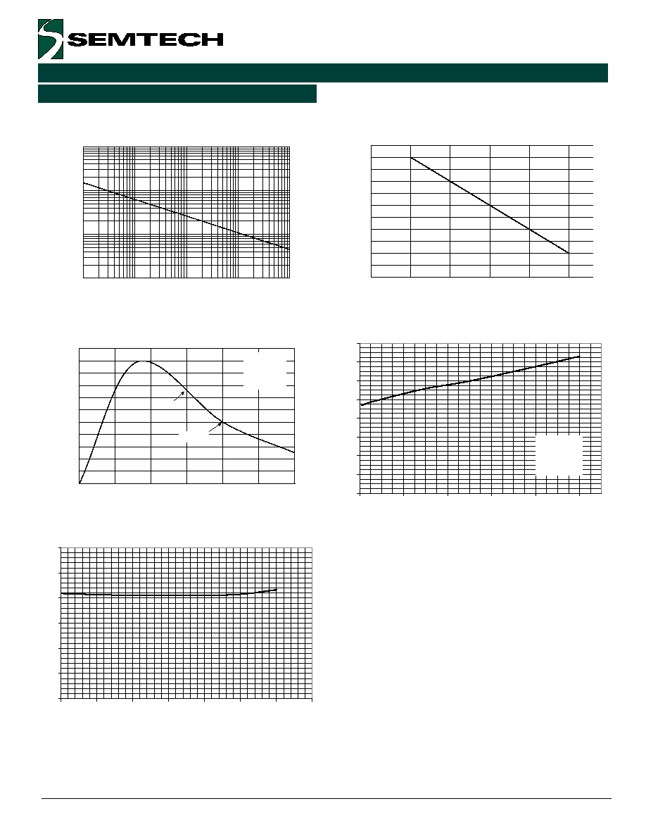
Typical Characteristics
Non-Repetitive Peak Pulse Power vs. Pulse Time
Power Derating Curve
Clamping Voltage vs. Peak Pulse Current
0
10
20
30
40
50
60
70
80
90
100
110
0
5
10
15
20
25
30
Time (
µ
s)
Percent of I
PP
e
-t
td = I
PP
/2
Waveform
Parameters:
tr = 8
µ
s
td = 20
µ
s
Pulse Waveform
Capacitance vs. Reverse Voltage
0
10
20
30
40
50
60
70
80
90
100
110
0
25
50
75
100
125
Ambient Temperature - T
A
(
o
C)
% of Rated Power or I
PP
0.1
1
10
100
0.1
1
10
100
1000
Pulse Duration - tp (
µ
s)
Peak Pul
s
e Power
-
P
PP
(k
W)
0
1
2
3
4
5
6
0
1
2
3
4
5
6
7
Reverse Voltage (V)
Cap
aci
t
a
n
ce (
p
F
)
0
2
4
6
8
10
12
14
16
0
20
40
60
80
100
Peak Pulse Current - I
pp
(A)
Cl
amp
i
n
g
V
o
l
t
ag
e -
V
c
(V)
Waveform
Parameters:
tr = 8
µ
s
td = 20
µ
s

4
„ 2000 Semtech Corp.
www.semtech.com
PROTECTION PRODUCTS
LC05-06
Figure 1 - Connection for Differential (Line-to-Line)
Protection of two Tip/Ring Line Pairs
Device Connection Options for Protection of Two
High-Speed Line Pairs
The LC05-6 is designed to protect four high-speed data
lines (two differential pairs) from transient over-volt-
ages which result from lightning and ESD. Protection
of two line pairs is achieved by connecting the device
as follows: Pins 1-4 are connected to line 1 of the first
pair (i.e. Tip 1) and pins 13-16 are connected to line 2
of the first pair (i.e. Ring 1). Pins 5-8 are connected to
line 1 of the second pair (i.e. Tip 2) and pins 9-12 are
connected to line two of the second pair (i.e. Ring 2).
All pins should be connected for best results. Minimize
parasitic inductance in the protection circuit path by
keeping the trace length between the protected line
and the LC05-6 as short as possible.
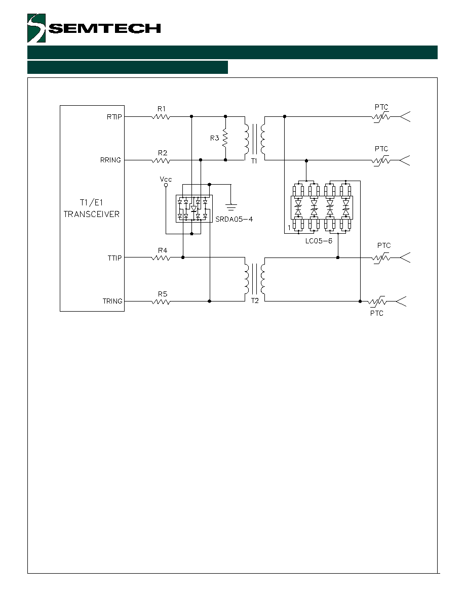
T1/E1 Linecard Protection
A typical T1/E1 linecard protection circuit is shown in
Figure 2. The LC05-6 is connected between Tip & Ring
on the transmit and receive line pairs. It provides
protection to metallic (line-to-line) lightning and ESD
surges. It is designed to meet the intra-building re-
quirements of Bellcore GR-1089. This design takes
advantage of the isolation of the transformer to
suppress common mode surges. To complete the
protection circuit, the SRDA05-4 (or SRDA3.3-4 for
3.3V supplies) is employed as the IC side protection
element. This device helps prevent the transceiver
from latching up by providing fine clamping of tran-
sients that are coupled through the transformer.
TIP 1
TIP 2
RING 1
RING 2
Applications Information
5
„ 2000 Semtech Corp.
www.semtech.com
PROTECTION PRODUCTS
LC05-06
Typical Applications
Figure 2 - T1 Line Card Protection

6
„ 2000 Semtech Corp.
www.semtech.com
PROTECTION PRODUCTS
LC05-06
Land Pattern - SO-16
Outline Drawing - SO-16

7
„ 2000 Semtech Corp.
www.semtech.com
PROTECTION PRODUCTS
LC05-06
Contact Information
Semtech Corporation
Protection Products Division
652 Mitchell Rd., Newbury Park, CA 91320
Phone: (805)498-2111 FAX (805)498-3804
t
r
a
P
r
e
b
m
u
N
g
n
i
k
r
o
W
e
g
a
tl
o
V
r
e
p
y
t
Q
l
e
e
R
e
z
i
S
l
e
e
R
B
T
.
6
-
5
0
C
L
V
6
0
0
5
h
c
n
I
7
E
T
.
6
-
5
0
C
L
V
6
0
0
5
2
h
c
n
I
3
1
Note:
(1) No suffix indicates tube pack.
Ordering Information