 | –≠–ª–µ–∫—Ç—Ä–æ–Ω–Ω—ã–π –∫–æ–º–ø–æ–Ω–µ–Ω—Ç: LP2951A | –°–∫–∞—á–∞—Ç—å:  PDF PDF  ZIP ZIP |
LP2951A
© 1998 SEMTECH CORP.
150mA ADJUSTABLE
VOLTAGE REGULATOR
March 17, 1998
652 MITCHELL ROAD NEWBURY PARK CA 91320
1
DESCRIPTION
The LP2951A is an improved version of the LP2951
and features tighter tolerance on the output voltage
and reference voltage specifications. Both the LP2951
and LP2951A feature 150mA output current capability.
The LP2951 series of low power voltage regulators
have low quiescent current and low dropout voltage.
The quiescent current increases minimally during
dropout conditions thereby extending battery life.
Available in the eight lead SOIC package, the LP2951
series includes features such as shutdown and low
output voltage detect (typically due to low battery con-
ditions) . This function may also be used as a power on
reset function when triggered by CMOS or TTL inputs.
The circuit can be used as a fixed voltage 5 volt regula-
tor or adjusted between 1.24 volts and 29 volts using
external resistor pairs.
FEATURES
∑
=
Guaranteed 150mA current
∑
=
Adjustable output voltage - 1.24V to 29V
∑
=
Accurate 5V output @150mA
∑
=
Low dropout voltage - 450mV @ 150mA
∑
=
Regulator or reference functions
∑
=
Direct replacement for LP2951AC, MIC2951-02,
AS2951AC
APPLICATIONS
∑
=
Microcontroller supplies
∑
=
Linear regulators
∑
=
Adjustable supplies
∑
=
Switching power supplies - post-regulation
∑
=
Portable modems
∑
=
Battery powered systems
∑
=
Cellular telephones
∑
=
Voltage references
TEL:805-498-2111 FAX:805-498-3804 WEB:http://www.semtech.com
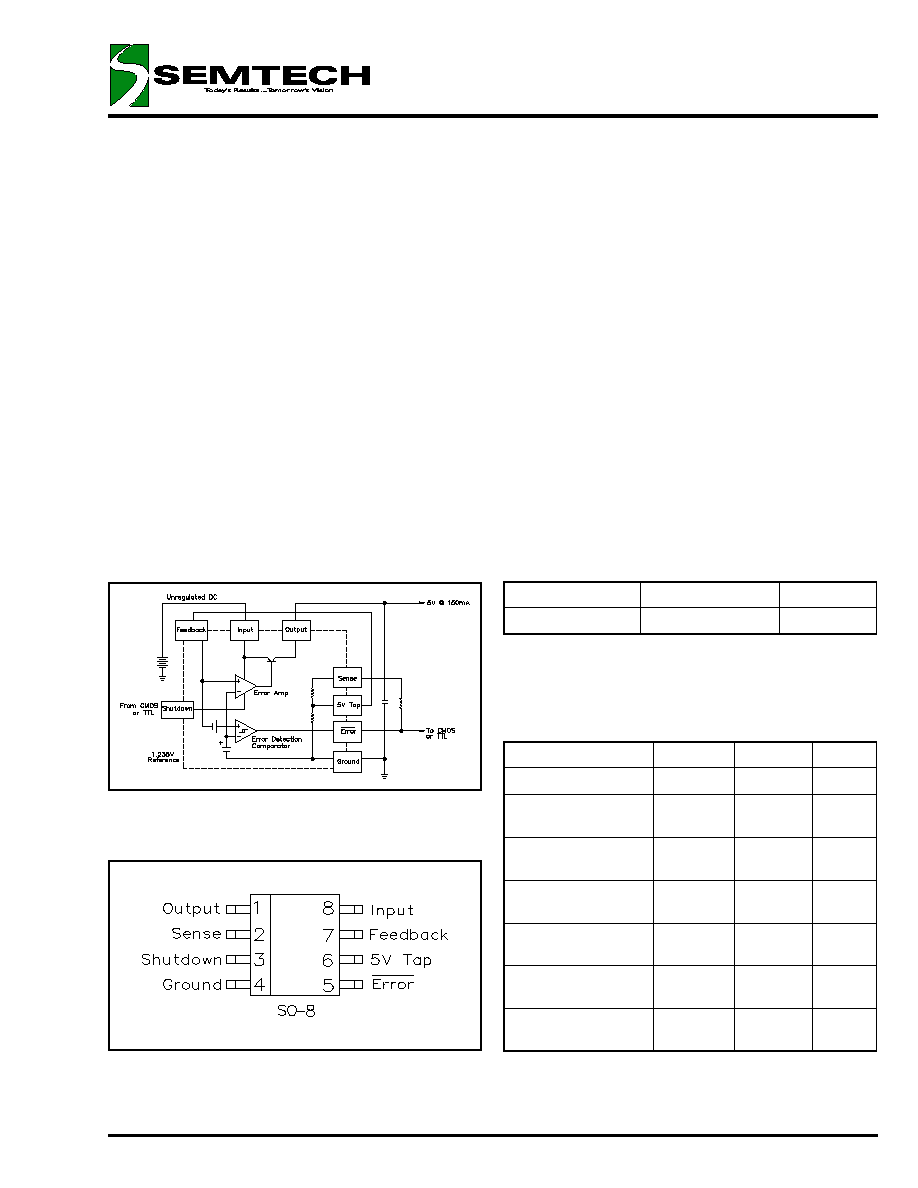
BLOCK DIAGRAM
PIN CONFIGURATION
ABSOLUTE MAXIMUM RATINGS
Parameter
Symbol
Maximum
Units
Supply Voltage
V
IN
-0.3 to 30
V
Shutdown Input
Voltage
-0.3 to 30
V
Error Comp. Output
Voltage
-0.3 to 30
V
Power Dissipation
P
D
Internally
Limited
W
Operating Junction
Temperature Range
T
J
-40 to 125
∞C
Storage
Temperature Range
T
STG
-65 to 150
∞C
Lead Temperature
(Soldering) 5 Sec
T
LEAD
260
∞C
ORDERING INFORMATION
Note:
(1) Add suffix `TR' for tape and reel.
DEVICE
(1)
V
OUT
VOLTS
PACKAGE
LP2951ACM
ADJ
SO-8

LP2951A
© 1998 SEMTECH CORP.
150mA ADJUSTABLE
VOLTAGE REGULATOR
March 17, 1998
652 MITCHELL ROAD NEWBURY PARK CA 91320
2
NOTES:
(1) Temperature coefficient is defined as the worst case voltage change divided by total temperature range.
ELECTRICAL CHARACTERISTICS
Unless specified, limits are over operating temperature range (T
J
= T
A
), V
IN
= V
OUT(NOM)
+ 1V, I
L
= 100µA, C
L
= 1µF
Parameter
Symbol
Conditions
Min
Typ
Max
Units
Output Voltage
V
OUT
T
J
=25∞C, I
L
= 100µA
4.975
5.000
5.025
V
Temp Coefficient
(1)
T
C
0∞C
T
J
=
70∞C
20
120
ppm/∞C
Line Regulation
REG
(LINE)
6V
V
IN
=
=
30V
0.1
0.5
%
Load Regulation
REG
(LOAD)
100µA
I
L
=
=
150mA
0.1
0.4
%
Dropout Voltage
V
D
I
L
=
=
=
100µA
80
150
mV
I
L
=
=
=
150mA
380
600
Ground Current
I
GND
I
L
=
=
=
100µA
120
160
µA
I
L
=
=
=
150mA
8
14
mA
Dropout Ground Current
I
GND(D)
V
IN
= 4.5V, I
L
=
=
=
100µA
110
250
µA
Current Limit
I
CL
V
OUT
= 0
200
250
mA
Reference Voltage
V
REF
V
REF
V
OUT
(V
IN
- 1V), T
J
=
=
25∞C,
100µA
I
L
=
=
100mA
1.22
1.235
1.25
V
Feedback Bias Current
I
FB
20
60
nA
Error Comparator
Output High Leakage
Current
V
OH
= 30V
2
µA
Output Low Voltage
V
IN
= 4.5V, I
OL
= 400µA
150
400
mV
Threshold Voltage
Upper
25
60
mV
Lower
75
140
Hysteresis
15
mV
Shutdown Input
Input Logic Voltage
V
SD
Low
0.6
V
High
2.0
V
Input Current
I
SD
V
SHUTDOWN
= 2.4V
100
µA
V
SHUTDOWN
= 30V
750
Regulator Shutdown
Output Current
I
O(SD)
V
SHUTDOWN
2V, V
IN
30V,
V
OUT
= 0, Feedback pin to Tap 5V
20
µA
LP2951A
© 1998 SEMTECH CORP.
150mA ADJUSTABLE
VOLTAGE REGULATOR
March 17, 1998
652 MITCHELL ROAD NEWBURY PARK CA 91320
3
PRINCIPLES OF OPERATION (LP2951 AND LP2951A)
V
235
.
1
1
R
x
10
x
20
2
R
235
.
1
9
+
˘
Í
Î
È
˜
¯
ˆ
Á
Ë
Ê
+
-
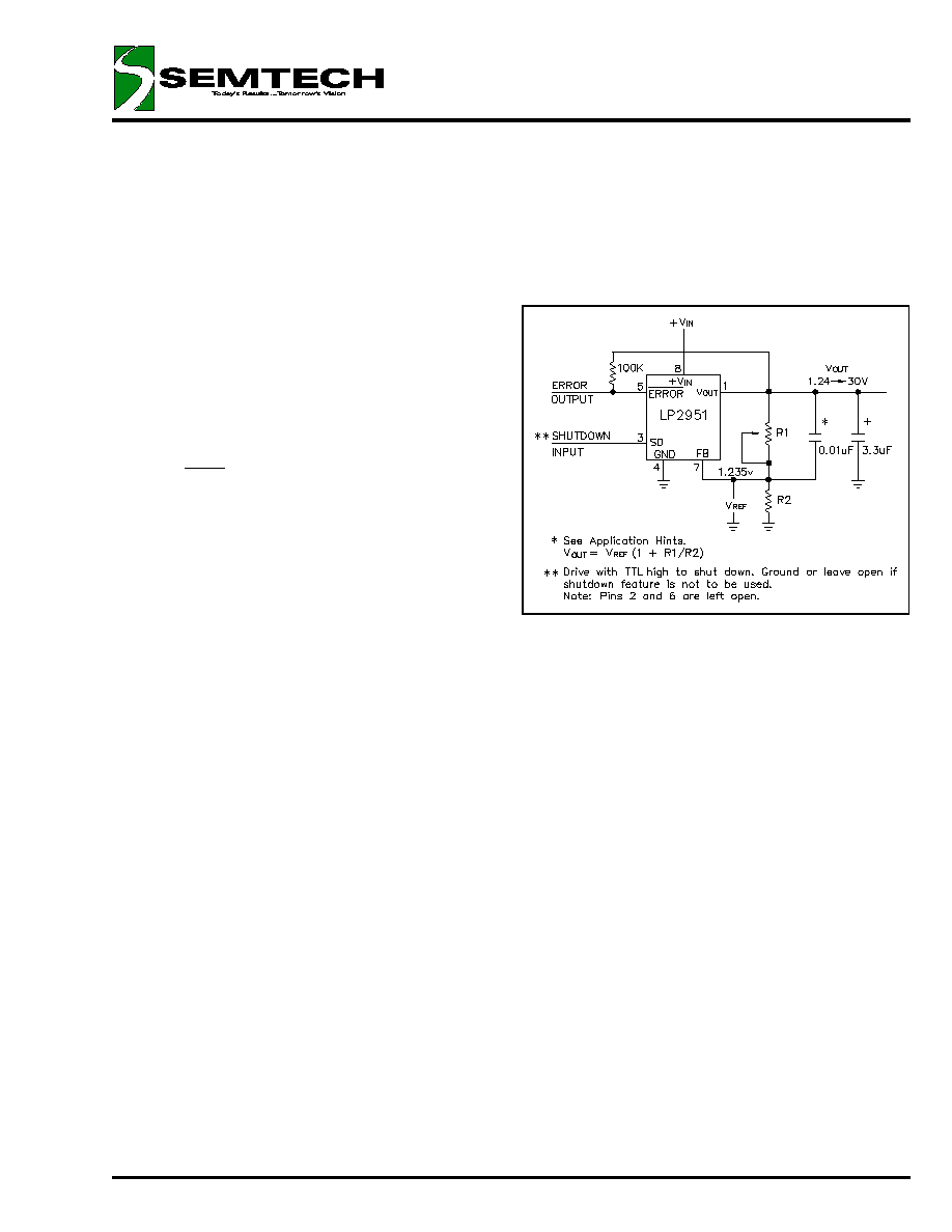
Setting the Output Voltage
The LP2951(A) can be set to deliver any output voltage
from 1.24V to 30V by using an external voltage divider.
In addition, an internal voltage divider is provided if a
5V output is desired. To use the internal voltage di-
vider, simply connect the sense pin to the output and
the tap pin to the feedback pin (see block diagram).
When using an external divider the sense and tap pins
are left open, and the divider is installed from the out-
put to ground, with its center connected to the feed-
back pin (see Adjustable Regulator figure below).
When using an external voltage divider, resistances
can be calculated from the following formula:
V
OUT
=
An upper limit of values for R2 occurs at ~1.2M
if the
regulator is to be operated when completely unloaded,
as this allows the feedback divider to provide the 1µA
minimum load recommended for the LP2951(A). If the
regulator always has a load of 1µA or more connected
externally, higher resistor values can be used, but at-
tention must be paid to the -20nA (typical) bias current
required by the feedback pin. Using a 1.2M
resistor
for R2, this bias current will already cause a 2% shift in
output voltage between full load and no load. Larger
values of R2 exacerbate the problem. Using a 120K
resistor for R2 reduces the error caused by feedback
bias current to 0.2% while still only requiring 10µA to
feed the divider string.
Output Filtering
An output filter capacitor is always necessary with the
LP2951(A) in order to assure output stability. The size
of this capacitor varies with output voltage (smaller at
higher output voltages) and output current (smaller at
lower output currents). For 5V operation 1µF is suffi-
cient. For regulator operation at a minimum output volt-
age, (1.24V) and output currents of 100mA, the re-
quired filter increases to 3.3µF. Any type of capacitor
may be used, although if aluminum electrolytics are
chosen, the equivalent series resistance (ESR) should
be held to 5
or less. For small load currents the ca-
pacitance can be reduced. 0.33µF will be satisfactory
for output currents of 10mA or less, and 0.1µF will
work if output current is below 1mA.
Theoretically, it is also possible for the regulator to be-
come unstable if very large capacitances (>10,000µF)
are connected to the output, but this has not been ob-
served in practice. It is also important that the capaci-
tance be mounted close (1cm or less) to the output pin
of the regulator.
Adjustable Regulator
If the lead inductance between the input of the
LP2951(A) and its power source exceeds ~500nH
(approximately 10"/25cm of 0.031"/0.78mm trace) it
may also be necessary to add a filter capacitor be-
tween the input terminal and ground. A 1µF tantalum
or aluminum capacitor is usually sufficient. Lower val-
ues can be used if load currents are small. Noise injec-
tion into the feedback terminal of the LP2951(A) from
nearby noise sources can also upset the output. Gen-
erally this can be cured by the addition of 100pF or so
from the feedback terminal to the output.
V
235
.
1
1
R
x
10
x
20
2
R
235
.
1
9
+
˘
Í
Î
È
˜
¯
ˆ
Á
Ë
Ê
+
-

LP2951A
© 1998 SEMTECH CORP.
150mA ADJUSTABLE
VOLTAGE REGULATOR
March 17, 1998
652 MITCHELL ROAD NEWBURY PARK CA 91320
4
PRINCIPLES OF OPERATION (LP2951 and LP2951A) (cont.)
Reducing Output Noise
In ultra-quiet systems, or when the LP2951(A) is being
used as a reference, it may be desirable to perform
additional output filtering to reduce noise. While this
can be done simply using larger capacitors on the out-
put, that solution tends to be bulky and expensive, and
eventually, with huge capacitors (>1,000µF) may cause
instability in the regulator. Generally, it is more cost-
effective to let the regulator regulate output noise
away. This can be done by bypassing the upper resis-
tor in the feedback divider with a small capacitor to
provide a more direct path for AC feedback. The size
of this capacitor can be calculated from the formula:
C
BYPASS
=
where R1 is the upper resistor of the feedback divider
and f
corner
is the frequency above which the increased
AC feedback is to become active. Because the gain of
the error amplifier in the LP2951(A) begins to roll off at
about 300 Hz, this is generally an optimum choice for
corner frequency.
The reduction of the output noise will be proportional to
the ratio of the two resistors in the feedback divider,
and will increase 20 dB per decade at frequencies
above the corner frequency chosen, up to the fre-
quency where the error amplifier's gain has rolled off to
1 (
100KHz). In order to maintain regulator stability
when using a noise-reducing bypass capacitor, it will
also be necessary to increase the size of the output
filter capacitor by the ratio
2
R
1
R
1
R
+
2
R
1
R
1
R
+
corner
1
f
R
2
1
LP2951A
© 1998 SEMTECH CORP.
150mA ADJUSTABLE
VOLTAGE REGULATOR
March 17, 1998
652 MITCHELL ROAD NEWBURY PARK CA 91320
5
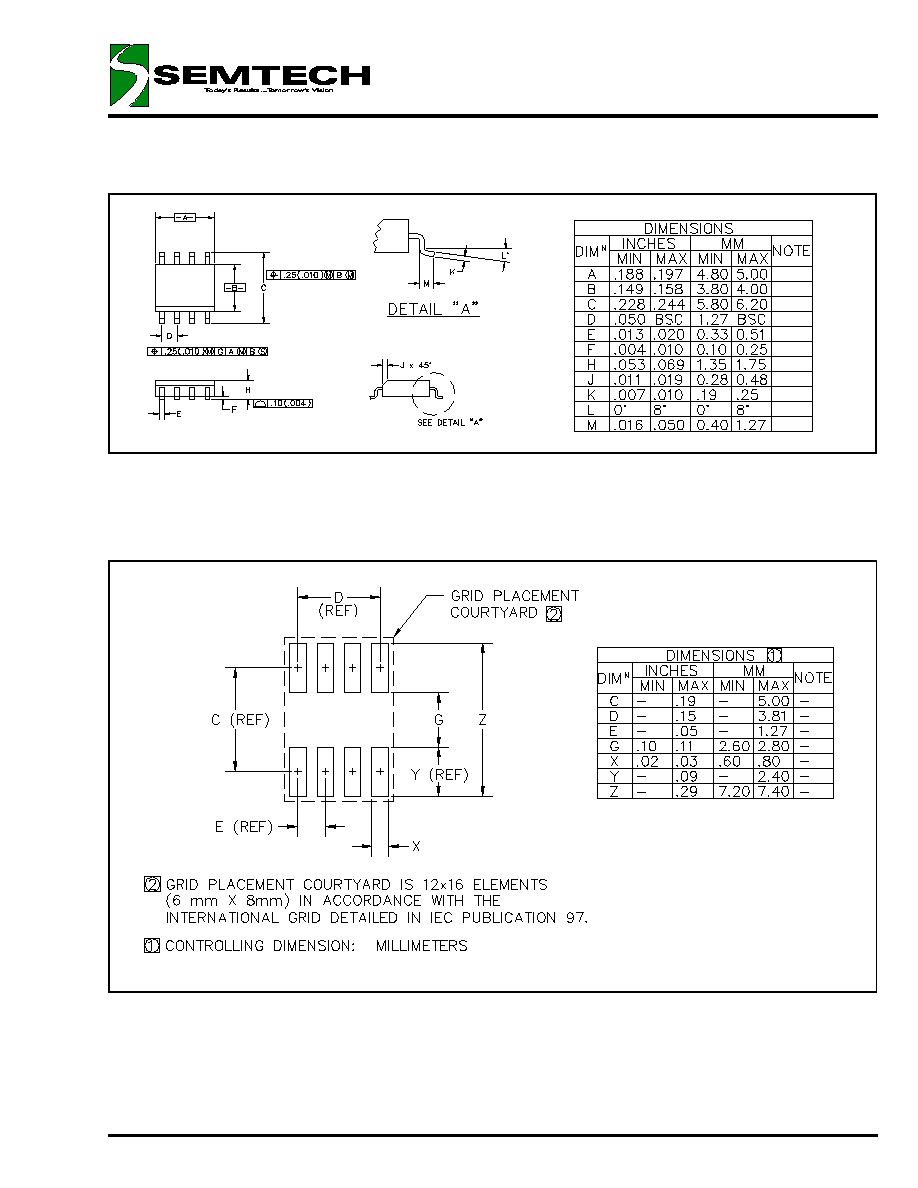
OUTLINE DRAWING SO-8
LAND PATTERN SO-8